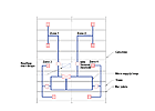
FIGURE 1. An example of duct runs in a mezzanine office space, featuring loop through joists.
A loop duct is a distribution layout that is joined at the ends. Supply air can feed a zone control device from two or more paths. This arrangement can be helpful when faced with any of the following circumstances:
- Ceiling space is limited;
- Air supply qualities vary as the solar load shifts;
- An expansion is planned for the facility;
- The system is being converted from a constant volume zoned arrangement to VAV;
- Redundant supply air is important; or
- Cost reduction of sheet metal ductwork is desired.
In this configuration, the duct distribution main becomes a supply plenum with higher velocities than are normally thought of for plenum designs. The air supply feeds a zone type of control. The zone device may be a traditional VAV box, a fan-powered VAV box, a zone isolation damper, or a VAV diffuser. The return air path is usually a ceiling plenum return-type.
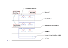
FIGURE 2. Vertical expansion with new loops.
ROOFTOP UNITS
A rooftop AHU is often used in a facility constructed with steel beams and bar/truss joists for the roof structure. The demand for high ceilings or two occupied levels often puts a demand on the space available for a duct distribution system. This space crunch may require the main supply duct to run in the web space of the bar/truss joists. Two or more parallel duct runs are required to adequately serve the area control outlets. Figure 1 shows an arrangement for a mezzanine office arrangement. Table 1 indicates the normal space available to the ductwork in the structural webbing.A facility with plans for vertical expansion is also project that can use the loop duct supply concept. Figure 2 shows how the existing unit is relocated (or replaced), and another unit is added to supply the new required capacity and joined into the original system.
SOLAR LOAD SHIFT
As the sun load moves around the perimeter of a building, the demand for the supply air also shifts. To avoid having to size the three normal sun exposure duct mains to handle the peak load, a loop duct can be used to supply the exposures from the two ends of the duct. The duct can be sized for one half calculated loads and the duct can supply from two ends of run sources.MODULAR UNITS
The use of factory-built modular units and a requirement for 24/7 redundancy offers another use of the loop duct concept. The selection of a 25-ton DX unit for an office area that required backup capacity (as well as expansion capacity) used the arrangement shown in Figure 3. The 25-ton units were cost-effective and would fit nicely in the available space. The redundant units can be located side by side and are connected to the common loop duct.Individual units have isolation low leakage dampers on the supply ducts and the return ducts. The units usually operate together; however, individual units can be started or stopped as the need occurs. The shutdown mode can be either for a planned or unplanned condition. Planned shutdowns are for cleaning, filter changing, and other maintenance. An unplanned shutdown will still provide about 80% of the design capacity.
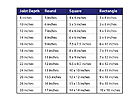
TABLE 1. Normal space available to the ductwork in the structural webbing.
FLEXIBLE DESIGN ARRANGEMENT
Facilities that have planned expansions or planned layout changes are candidates for the loop duct arrangement. A facility that requires expansion or area remodeling as the business grows can have planned loop duct connections to add to the capacity of the overall system. A mechanical room in the new addition contains an AHU selected to match the capacity of the other existing units. One uniform size is selected to facilitate maintenance parts and the ease of stopping and starting any one of the units.Area remodels can be handled by isolating the branch air-handling system serving the remodel area, then adding or subtracting any zone VAV terminals. The new branch ductwork can then be installed. When the new duct layout is completed, the isolation dampers are opened and the system will supply the required supply air. The alternative is often to demolish an existing system and replace it with a new air handler and all new ductwork.
CONVERSION OF A CONSTANT VOLUME SYSTEM TO VAV ARRANGEMENT
Constant volume branch ducts are designed to supply air to spaces based on design calculations. If the facility is being converted to a VAV zone control system, the original supply ductwork is often demolished. The system can be converted to a loop duct system by removing only the end of the small duct and extending the next duct size to join the ends of the ducts. This conversion is shown in Figure 4. The original ductwork should be leak sealed to be able to handle static pressures of 1 in. w.c.The new branch ductwork is taken from this loop duct main, directed to the zone control box or damper, and then distributed to the new terminal layout.
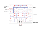
FIGURE 3. An example of a modular ducts used with a 25-ton DX unit for an office area that required backup capacity.
BENEFITS OF LOOP DUCT DESIGNS
All system-sizing exercises arrive at two duct solutions: the duct system may be too large or too small for any given condition. There is never just the right size for any variable capacity system. Using the loop duct, a system can be sized for smaller or larger operating conditions. The system capacity is dictated by the varying of the supply fan. The loop duct can be constructed of round, flat oval, or traditional rectangular/square configurations. The round or flat oval ducts can be run in longer lengths, which require fewer duct hangers. The branch take-offs can be cut-in later in the construction schedule. This later cut in allows more direct branch runs to the spaces served. The use of one or two main duct run sizes also reduces the cost of transformation fittings.Round or flat oval ducts have better sound characteristics in regard to low-frequency rumble. Double-wall, sound-treated sections of duct runs can be used in sound critical areas.

FIGURE 4. An example of a loop duct configuration in the conversion from a constant volume system to a VAV system.
HOW TO DESIGN THE SYSTEM
Calculate the amount of supply air needed for all the spaces. Using these calculations, select fan/unit capacities that will meet the design cfm and arrive at duct paths that can supply the air from two directions.The air supply units should be all the same size and configuration. This decision is based on uniformity of maintenance items, typical spaces required for unit space, and familiarity for the operation staff. Each unit should have variable capacity based on duct static pressure requirements. The static pressure sensors are located away from the fan about 2/3 of the distance to the farthest terminal. Sensor averaging can be used in multiple supply unit systems. Each unit must have a low leakage isolation damper. A good location for this damper is in the mechanical room wall. Care should be taken to locate any damper filler at the lower portion of the duct to avoid any high velocity turbulence, which often occurs at the top portion of the duct this close to the supply fan.
Duct design velocities for rectangular/square configurations should be in the 1,600 to 1,800 fpm range. Round and flat oval ductwork can use higher duct velocities in the 1,900 to 2,300 fpm range. The higher velocities in the round/flat oval ductwork are due to the profile of the duct and more even velocity profiles through the duct runs.
The outdoor air ventilation for the facility can be evenly divided among the online units. Using this strategy, the units can have dedicated outdoor air, two position dampers, and a modulation damper for the economizer cycle. The units can also have dedicated two-position outdoor air dampers for kitchen exhaust and dish machine exhaust replacement air. In laboratory or industrial facilities with varying exhaust rates, the outside replacement air component must be maintained using a building pressure control.
CONCLUSION
The concept of loop supply ducts reduces the size of the ductwork, uses less size reduction fittings, simplifies the duct runs, and allows for system expansion and area duct layout changes that occur in remodeling, as well as the reuse of constant volume duct runs to be converted to variable volume systems.The use of multiple supply air units feeding into the loop duct allows for redundancy and spare capacity for the future. The spare capacity control is by means of the variable-speed controls on the fan system. Added fan capacity and loop duct paths can be added and interconnected as the facility is expanded or remodeled.
The design engineer needs to take a deep breath and be comfortable that there is no right size duct; the higher velocities noted in this article do work fine and do not create noise problems.


