Figure 1. The traditional response of a system pump hp
in changes to demand/flow.
Commercial system experts see flow as a key step to optimizing system efficiency. Cutting down required tubing size, insulated PEX for district systems, and variable-speed pumps to pin down a chiller’s exact needs are three points of attack in the modern campaign against waste.
Commercial hydronic and domestic water systems are being scrutinized by experts nationwide. Although the close inspection of operation and efficiency likely won’t inspire a “CSI: Mechanical Systems” television series, there’s certainly no lack of interest by commercial system pros.
It’s the sort of shake-up that invariably happens when new technology provides a better way of doing things. In this case, smart, variable-speed pumping is the core of an exciting, burgeoning paradigm shift.
Why all the attention? Because the benefits are numerous, affecting overall systems, key components, operational efficiency, and performance. Some experts believe that what we’re seeing now is the broad application of technology whose time has finally come.
What’s refreshing is the objectivity of the movement. It’s not about ECM motors that offer a small, though cumulative advantage in energy use. It’s not about a new pump impeller design, or high-tech pipe lining, or pipe-joining technique.
It’s all about flow.
Let’s admit: there’s no more important, all-encompassing facet to the design, installation, or retrofit of large, pumped water systems than to reduce flow to its essential need.
To move beyond the theoretical and into the practical application of new influences to system flow, I turned to two experts, both well recognized in their fields: Watts Radiant’s John Sweaney, hydronic product manager, and Taco’s Bryan Payne, Southeast commercial regional manager.
SPEAKING HYDRONICALLY
Sweaney, who’s studied large system flow for nearly two decades, says that, whether it’s flow on the heat-source side or flow on the load side, there’s a huge focus on energy efficiency, and fluid flow is at the center of the movement.“Many things can be done to minimize flow, yet maintain or optimize comfort or performance - that’s the key,” said Sweaney.
“We often look at Delta-Ts [or “DT:” the temperature difference between supply and return water temperatures] from a design standpoint, especially if it’s a commercial system like a shop, warehouse, or snowmelt system. Installations like these call for larger Delta Ts - 30° or more - which reduce system pumping requirements.”
Cooler return water temperatures also play nicely into the use of efficient heating systems, like modulating-condensing boilers which purposefully harvest Btu’s from condensation that forms within the system, geothermal heat pumps, and water-sourced heat pumps.
Though ideal Delta Ts for most hydronic systems is a comfort/consistency issue, targeting 10°, 15°, or 20°DTs, many larger systems can be designed to meet the very most basic comfort or performance requirement while conserving energy across the board.
“With many properly-designed commercial systems, we can ease up on flow requirements to the point where fuel use and pump size (and type) are substantially influenced . . . all leading toward enhanced system efficiency.
“The key exception is with snowmelt systems where performance can’t be compromised,” added Sweaney. “I’m referring to systems that are installed to remove ice and snow in critical ASHRAE ”Class III” areas like emergency room entries, hospital steps, and helicopter landing pads. Typically, we do not recommend a design calling for a Delta T greater than 30°, though for critical areas, the required Delta T should be 20°.”
When designing hydronic systems - whether radiant, snowmelt, or for high-temperature fancoils, or baseboards - there’s a direct relationship between the DT and flow. “Double the Delta T and cut the flow in half,” explained Sweaney.
The benefits of a reduced Delta T stretch beyond a reduced need to burn fuel at the heat source. “It extends to pumps of lesser size meeting the need and the down-sizing of piping, fittings, valves, and other components,” added Sweaney.
“A change in Delta T for a snow melt system could mean the ability to cut the flow rate from 40 gpm to 20 so that instead of 2-in. distribution copper, it could be reduced to 1.5,” he continued. “This could also mean a reduction in the size of the distribution manifold and smaller radiant tubing, or perhaps a more frugal layout.”
Sweaney referred to two key trends that we’ll look at next.
- District heating and cooling with insulated PEX. “This is one we’re seeing
more of as the green revolution has taken off,” began Sweaney. “Central,
district heating applications have grown substantially over the past couple of
years with the use of super-insulated PEX distribution lines to carry the Btu’s
between a central plant and, say, living units. New military housing
developments are using this approach.”
The use of insulated lines often accompanies the application of alternative energy sources such as biofuel, biogas, geothermal, and solar at prisons, universities, and apartment complexes. In Alaska, a military installation heats all housing units hydronically with waste heat recovered from the on-base electric power plant. Smart!
Another similar application is the use of insulated PEX, trenched underground, to carry injection loop Btu’s to remote locations.
- Variable-speed pumping to enable variable flow. Sweaney led us directly into this one, although we’ll turn to Taco’s Payne for insights into a burgeoning trend: the application of variable drives to all pumps, both constant and variable flow.
According to Payne, the application of VFDs to constant speed pumps is now the fastest growing segment of the commercial pumping industry, a trend that improves the performance and efficiency of both large domestic water and hydronic heating and cooling systems.
Since ASHRAE 90.1 was adopted by many states as their energy code (early to mid 90s), the shift in the HVAC industry of applying drives to system distribution pumps has been substantial.
“The pumps most commonly retrofitted by upgrading the electrical starters to VFDs for quick payback are of larger horsepower, serving loads that vary,” said Payne. “The benefits are dramatic, so we’re now seeing quick response in the industry to make the improvements; it’s the low-hanging fruit.”
According to Payne, in the last eight years, two trends have greatly encouraged the adoption of VFDs into more applications. The first is that the cost of drives is decreasing. Secondly, manufacturers have rushed to add features and functionality.
The advantages to retrofitting constant-speed pumps with VFDs include:
- Greater energy efficiency
- More precise flow control
- Soft-starting and stopping of motors to prolong pump life
- The integration of BMS communication
- Better balancing with speed control vs. imparting ‘false’ head
- Installing the ability to easily adjust flow to rerate energy plants when system flow gets out of balance or experiences reduced Delta T
“In very general terms, most pumps are designed with a safety factor of 10% to 20%. This is a legitimate, useful practice that allows for flexibility to accommodate a different mix of equipment to be installed other than what was specified, or future expansion,” continued Payne.
“For instance, this might mean that a pump selected at 1,750 rpm with a safety factor on the design head was installed, started up, and over-pumped the system because it was designed with a ‘little extra’ capacity. At this point, the test and balance contractor would take the discharge balancing valve and throttle it back - imposing “false head” - to move the pump back to design flow.
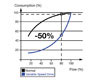
THE PUMP AFFINITY LAW
According to Payne, the newer, best industry practice being adopted is to use a drive to balance the pump while using the discharge valve as a flow measuring point, not a throttling point.Pump affinity laws help evaluate what the savings are for most jobs. The laws say that the change in horsepower consumed is proportional to the cube of the change in speed.
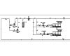
Figure 2. The system pumps, P-3 and P-4, have been the
obvious targets for VSDs and the industry has been applying drives to these
pumps across the board. Pumps P-1 and P-2 are the next to be optimized.
“Doing the math shows us that 80% (0.80) cubed is .512 and 90% (.90) cubed is .729,” explained Payne. “This means that a constant speed pump set up and balanced with a drive consumes only 73% of design horsepower if it has a 10% safety factor; a pump with a safety factor of 20% consumes only 51.2%” (Figure 1).
“These are significant energy savings,” continued Payne. “Other benefits for constant speed pumps installed with drives is that they’re now running at reduced speed which extends their life, and they’re also soft-started as a function of the drive. This puts less wear on pump and system components. These become an advantage for the equipment and the building owner.”
“With the focus on first cost, green construction and energy optimization, our industry needs advantages like these,” said Payne. “The decisions we make about design Delta T and flow balancing can have a significant positive impact on system performance.”
The system pumps P-3 and 4 in Figure 2 have been the obvious targets for VSDs. The industry has largely transitioned to applying drives to these pumps. The industry is now adopting the chiller pumps P-1 and 2 as the new target to optimize.
In Figure 3, a vertical inline pump being installed with a VSD. Many in the industry now see that significant savings can be achieved by balancing constant speed pumps with drives.
EXAMPLE
Referring to Figure 4, let’s look at startup, test, and balance for a primary, constant speed, 60-hp chilled water pump designed to serve a 1,500-ton chiller. It has a duty point of 3,600 gpm at a head of 55 ft. The pump selected for this job would be a 12-in. vertical, split coupled pump with a 12-in. dia impeller.
OLD SCHOOL BALANCING
Test and balance professionals go to the jobsite and measure the differential pressure across the pump with no balancing or throttling. The balance contractor would read a differential across the pump of 52 ft total dynamic head (TDH). This results in an unbalanced flow of 3,900 gpm.At this point, a choice presents itself: the pump can be balanced by imparting false head, or an old-school balancing technique could be used by taking the “actual “ system curve and laying it over the pump curve. The curve can be traced down to the required system flow (3,600 gpm). Then install a trimmed impeller of 11.5 in., spinning it at 1,150 rpm.
This was very effective back in the day when on-site professionals had more time to construct, commission, and tweak mechanical systems. Today, with many jobsites immersed in tight project schedules, the thought of opening a pump to install a new impeller is impractical.
NEW SCHOOL ADVANTAGE
The contemporary method of achieving system balance and pump setup is for the design/specifying engineer to choose pumps matched with a VSD.At initial startup, there would be an unbalanced differential across the pump of 52 ft, just as it was before. This permits the ability to plot the “actual system” curve as shown in Figure 4. The startup point is labeled point B on this curve. The new “actual system” curve is now traced to where it intersects with the design flow of 3,600 gpm. This point is labeled “C” in the diagram.
FIELD SETUP
Here, pump affinity laws help to explain how the drive achieves optimal flow, not by trimming an impeller but by altering pump speed.Speed change Impeller diameter change
Flow:
Q2 = Q1 X (N2/N1) Q2 = Q1 X (D2/D1)
Head:
H2 = H1 X (N2/N1)2 H2 = H1 X (D2/D1)2
H2 = H1 X (N2/N1)2 H2 = H1 X (D2/D1)2
Horsepower:
Bhp 2 = Bhp 1 X (N2/N1)3 Bhp 2 = Bhp 1 X (D2/D1)3
Bhp 2 = Bhp 1 X (N2/N1)3 Bhp 2 = Bhp 1 X (D2/D1)3

Figure 4.
Pump curve schematic showing the “actual system” curve alongside the design
curve.
“The ratio of impeller trims will tell us the new speed,” explained Payne. “We started with a 12-in. impeller; if we had done it the old-school way, the impeller would’ve been trimmed down to 11.5 in. Instead, we take the ratio of 11.5 to 12, which is .958. Taking 95.8% of 60 Hz, our new max speed on the drive is 57.5 Hz. Doesn’t sound like much, does it?”
BIG BANG FOR THE BUCK
According to Payne, this helps to explain how a 60-hp constant speed primary pump with a drive can be set up to pump exactly what the chiller needs without having to induce false head. The original bhp at Point A would have been 55.3 hp. The new hp at point C will be 45.1 hp, or a savings of 10.2 hp.If the application would be a hospital where the cooling load is 24/7/365, the use of a drive would result in an annual energy savings of about $5,000. What’s noteworthy in this scenario: Payne points out that $5,000 is coincidentally roughly the cost of such a drive, with the savings providing a one-year ROI for the upgrade, water and utility savings notwithstanding.ES


