
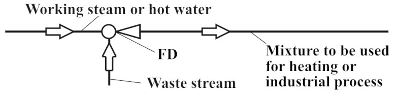
Fisonic Devices (FDs) are heat exchangers, pumps, and mixers with patented optimized internal geometry. The theory of Fisonic devices was developed by Professor Fisenko by addressing safety problems of the Russian nuclear submarines during the disruption of the air tightness of reactor cavity (Ref 1-2).
The diagram of an FD is presented in Figure 1. At this design, the injected water enters the mixing chamber with high velocity in parallel with the velocity of the working stream. The injected water is supplied through a narrow circumferential channel surrounding the working nozzle. The mixing chamber has a conical shape. The FDs operate with high expansion and small compression ratios. The discharge pressure in the FDs is typically higher than the pressure of the working and injected streams.
> FIGURE 1. The Fisonic Device diagram.
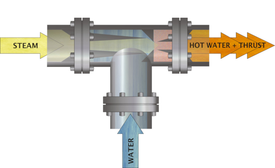
Dr. Fisenko has demonstrated that uniform two-phase flows have more compressibility than the flows of pure gases. Hence the possibilities of the more effective conversion of thermal energy into the mechanical work in uniform two-phase mixtures, especially in the transonic or supersonic modes. The optimized internal geometry of the FD causes the working and the injected streams to mix and accelerate, creating transonic conditions and converting the minute fractions of the streams’ thermal energy to physical thrust (pump head) with the discharge pressure higher than the pressure of the mixing streams. The main reason behind this phenomenon is the high compressively of homogeneous two-phase flows. The sonic speed in such systems is much lower than the sonic speed in liquids and in gases. As one can see from Figure 2, the minimum sonic velocity takes place at the volumetric ratio of the streams of 0.5 (Ref.3).
> FIGURE 2. The dependence of sonic speed on volumetric ratio of streams.
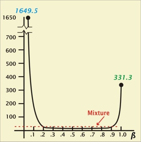
Where:
S = sonic velocity, m/s.
β = ratio of volumetric gas to liquid plus gas composition
From Figure 2, one can see that when there is no liquid, the ratio β equals one. If there is no gas, the ratio β equals zero. When there is 50% liquid and 50% gas (two phase flow) – the ratio β is equal 0.5 and the sonic velocity is much lower than in gases and liquids.
The equation of sonic speed is as follows:

Where:
k = isentropic exponent, equal to the ratio of specific heats; P = pressure;  = density of the medium.
When the transfer from the supersonic flow conditions to the subsonic is achieved in the jump, the compressibility of the uniform two-phase flow determined by Mach number depends only on the volumetric ratio β of components in the mixture and does not depend on the properties of gas and liquid in the mixture. Dr. Fisenko demonstrated that in the FDs this jump can be isentropic. In this case, in the uniform (fog-like) two-phase flow, the momentum exchange mechanism between the phases is based on elastic interaction of gas molecules with the finely dispersed liquid particles and the pressure jump mode prevails over the heat exchange process.
Currently, officially certified small-scale manufacturers of FDs are mass producing the FDs for numerous energy conservation applications in Russia, republics of the former USSR, and China. More than 200 major installations have demonstrated a reliable and efficient operation of FDs. The demonstration of the operational features of the FDs in the U.S. was performed by HFC under the sponsorship of NYSERDA and Con Edison Company of New York (Rev.4).
> FIGURE 3. A district steam system with a Fisonic Device. In the image, No. 1 represents a temperature controller; 2 – a non-return valve; 3 – FD; 4 – electric driven pump; and 5 – district heating customer.
Application of Fisonic Devices
The FDs can be used for many heat transfer, mixing, and pumping applications. Some of them are as follows:
- Replacement of surface type heat exchangers for space and district heating, power plants, and various industrial applications;
- Waste heat recovery systems;
- Space cooling applications;
- Replacement of electric driven pumps;
- Deaeration processes;
- CHP applications; and
- Various industrial processing and functional applications (i.e. washing, pulverization, proportioning, mixing, etc.).
District Heating
Many cities in the U.S. (New York, Boston, Philadelphia, and Indianapolis) have district steam systems. For example, Consolidated Edison Company of New York (Con Edison) currently serves with district steam about 1,600 large customers in Manhattan. The customers use the steam for space heating, domestic hot water, and cooling (through steam driven or absorption chillers). A number of customers currently convert the district steam into hot water in tube and shell heat exchangers. The hot water is then distributed by electrically driven pumps throughout the building for space heating and domestic hot water service. The steam condensate is discharged into the city sewer system. The discharge of the condensate consumes a substantial capacity of the sewer system and the sewer treatment facilities. In order to reduce the temperature of the discharged stream to 150°F, the condensate is mixed with cold potable water, thus further aggravating the sewer system problems.
Use of FDs in buildings can improve the end-use energy efficiency and significantly reduce the environmental impact of the steam based customers. The FD heats the recirculated building water by direct contact with steam and transports the water throughout the building, thus eliminating the tube and shell heat exchanger and the electrically driven pump. The use of the FDs allows reducing the terminal temperature difference between steam and water, the required steam consumption, and the amount of cold potable water.
The economic motivation for the customers for using the FD is the reduction in capital, maintenance and operating cost, a reduction in emission discharge to the environment, and the potential for waste energy recovery and utilization.
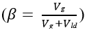
An example of FD use for a district steam heating application is presented in Figure 4. In this application, the FD replaces the surface-type steam to hot water heat exchanger and the hot water electrically driven circulating pump. The space heating requirements of the building are closely related to the outdoor temperature, which varies. For example, for New York City, from minus 1° to 60°. To control the building space heat supply, the working steam flow rate throughout the FD should vary in accordance with changes of outdoor temperatures. At these conditions because of the close relationship between the thermal and hydraulic modes of the FD, the discharge pressure and the water flow rate will vary. In order to keep the discharge water flow constant an electric driven pump is installed. The pump will operate for a limited number of hours during the year.
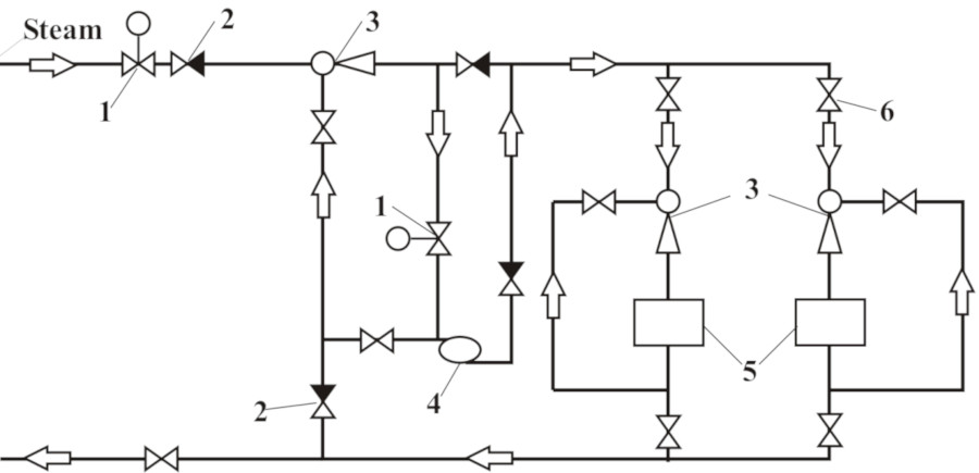
> FIGURE 4. A district steam/hot water system with FDs. In the image, No. 1 represents a temperature controller; 2 – a non-return valve; 3 – FD; 4 – pump; and 5 – district heating customers; 6 – valve.
The FDs can also utilize hot water as a working media. In this case, it is beneficial to increase the temperature difference between supply and return temperatures. A principal diagram of such a system is presented in Figure 5. In the central district heating plant, the steam supplied from a power plant or by boilers heats the district return temperature. The heated water is supplied through a district heating system to the district customers. Each customer is equipped with a FD where the district supply water heats the building return water from 160° to 190°. About 20% of the total water flow rate circulates in the district heating system and 80% in the customer systems. Customer FDs not only heat the water but also operate as circulating pumps at the customer systems.
> FIGURE 5. A diagram of waste heat recovery with an FD.
Waste Heat Recovery
A diagram of waste heat recovery system with FDs is presented in Figure 6. The FD can use any available steam or hot water as a working media and increase the temperature level and pressure of the waste stream of energy
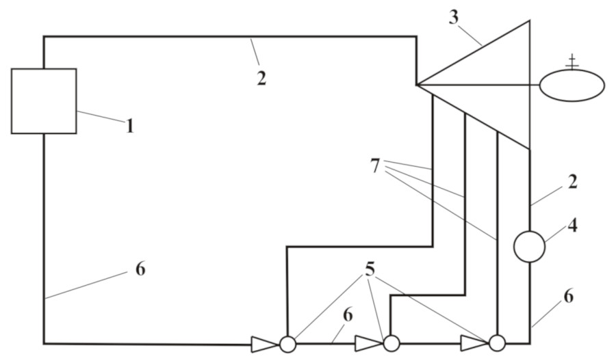
> FIGURE 6. Diagram of a power plant with FDs. In the image, No. 1 represents a steam generator; 2 – steam; 3 – a steam-turbine generator; and 4 – a condenser; 5 – FDs; 6 – Feed water; and 7 – extraction steam.
Waste Water Industry
The wastewater industry consumes a large amount of energy to process waste water. With escalating costs, this is becoming a big problem. As a solution to this, the industry has been very focused on capturing the methane from the effluent for use as a gas in combined heat and power plants (CHP). For some time now, the industry has been investing in and improving the digester process and taking the gas to a CHP plant. That power is used at the plant or put on the grid and the heat is used in the digester process.
The wastewater with the right concentration of effluent is directed into the FD and properly matched with the steam rate. The FD will breakdown the particles separating the gas. The gas is siphoned off, and the treated hot water is discharged from the FD. The gas is fed to a properly sized CHP module, which would generate electricity and heat for a self-sustained cycle with the FD. The output hot treated water could be fed to an advanced heat recovery device to further generate power or heat an existing digester gas application on-site.
Electric Generating Plants
The replacement of surface-type feedwater heaters with direct contact heaters for improvement of cycle efficiency has been under development for many years. The use of FDs as direct contact heaters allows simplification of the conversion and elimination of feed water pumps. An example of application of the FD in an electric generating plant is presented in Figure 6. In this plant, surface type feed water heaters are replaced with FDs, providing direct contact heating and pumping of the feedwater.
Space Cooling
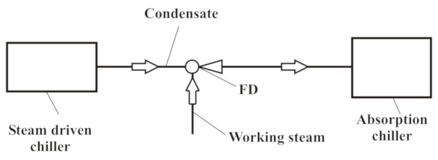
The application of the FDs for space cooling is presented in Figure 7. In this system, the temperature and pressure of exhaust condensate from a steam driven chiller is increased in a FD and used to generate additional space cooling in an absorption chiller.
> FIGURE 7. A space cooling application with FDs.
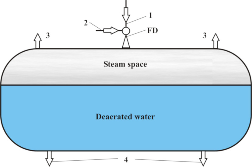
Water Treatment and Deaeration
The use of the FD in the deaeration process is presented in Figure 8. In this system, the FD is replacing the standard deaeration column, reducing the size of the deaerator and increasing the efficiency of the deaeration process. The FD can also be used for condensing the deaerator vapor and preheating the makeup water. Applications include vacuum, atmospheric, and high-pressure deaerators. The system advantages include smaller installation footprint and weight, a considerably wider range of stable operational parameters, and substantial capital and operational cost reduction.
> FIGURE 8. A deaerator with an FD. In the image, No. 1 represents working steam; 2 – makeup water and condensate; 3 – steam vapor with noncondensable gases; and 4 – exit of deaerated water.
References
- Fisenko, V.V. Critical two-phase flow systems, Moscow, Atomizdat, 1978.
- Fisenko, V.V. Compressibility of Heating Medium and Effectiveness of Operation of Circulation Loops of Nuclear Reactors, Moscow, Energoatomizdat, 1987.
- Fisenko, V.V. The Fisonic Energy Device. Joint Power Conference. Minneapolis, MN, October 1999.
- Demonstration of Performance and Energy Efficiency of Fisonic Devices at the Con Edison Test Facility. NYSERDA Report # 13-27, 2013.


