
Many multifamily, public housing apartment buildings are equipped with electric resistance baseboard heating systems, which are affordable to install. However, these systems have the several disadvantages, including:
- High operating electric cost (the coefficient of performance [COP] is close to 1);
- Safety hazards (high temperature of the heating surfaces);
- The heated room air space may be dry (which can cause dry skin, throats, and eyes); and
- Decomposition of indoor dust on the high heating surfaces (which may release volatile organic components in the leaving space1).
Practical experience has demonstrated that conversion from electrical to hot water space heating and domestic hot water (DHW) can be expected to reduce the energy cost for heating by more than 20% in most cases. When a large stock of electrically heated multifamily housing is located in urban areas with the possibility for district heating, there is the potential for large, cost-effective energy savings from converting to hot water space heating. Thus, with the large stock of electrically heated multifamily housing in the U.S., there is the potential for large, cost-effective energy savings from converting to hot water space heating.
The objective of this project was to demonstrate the practicality (effectiveness) of the conversion of electrically heated multifamily houses to hot water heating. Three multifamily buildings with electric resistance baseboard heating were selected for conversion using the Jamestown District Heating System as the source of heat2. The benefits of hot water district heating are well-established in Jamestown, which helped ensure the successful implementation of this project. The local utility welcomed both the reduction in electrical demand and the increased load for the district heating system.
W.B. Anderson Towers
W.B. Anderson Towers is a four-story, 38-apartment building without a basement. The building was constructed using a steel frame and cement block for exterior walls to separate apartments and enclose stairwells. The remaining interior walls are constructed of sheetrock. The top three floors of the building are arranged with a central corridor with six apartments on one (the building front) side and five apartments on the other. The first floor contains five apartments, a lobby, a tenant storage area, and the mechanical equipment room (MER). There are 22 one-bedroom apartments, five two-bedroom units, and the remaining 11 apartments are efficiency units. The efficiency units are identical to a one-bedroom apartment except there is no wall between the living room and bedroom. The one-bedroom apartments and efficiencies are typically 450 square feet in area while the two-bedroom apartments are 650 square feet. The building is located approximately 50 feet from the district heating underground piping system.
The heating system consists of electrical resistance baseboard elements. All the outside walls had this type of element installed. A typical apartment consists of a living room and bedroom along an exterior wall, and a bathroom and kitchen along an interior wall. Both the bathrooms and kitchens each have their own exhaust fans. There is a central makeup air unit located on the roof that pumps air into the corridor on each floor. This air is heated in the winter, originally using natural gas. The unit only runs during the daytime. Its purpose is to make up any air that is lost through an exhaust fan or by opening the outside doors. By providing an excess of makeup air over exhaust, the building is maintained at a slight positive pressure with warm air, and the occupants do not experience cold drafts when exterior doors are opened or when exhaust fans are operated. The domestic hot water was generated in three natural gas-fired heater/storage tanks located on the ground floor. The heaters maintained water at 120°F.
The monthly electric bills were obtained and normalized in accordance with 30-year heating degree days. Comparison of summer and winter bills allowed the electrical consumption for space heating to be estimated. Adequate space was available in the existing MER for the necessary district heat exchanger, valving, controls, meters, and piping. No technical or other obstacles to the conversion were identified.
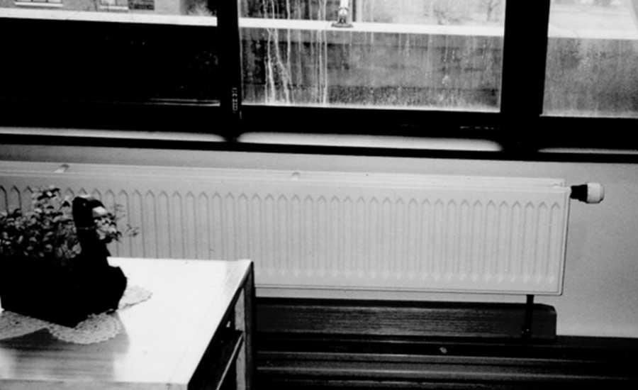
The conversion used a combination of equipment and installation techniques that minimized conversion costs, caused minimal inconvenience to tenants, and resulted in aesthetically acceptable configurations. Stamped steel radiators (panels) (see Figure 1) were used in place of baseboard-mounted finned tubes. The stamped steel radiators operate with a 36° temperature drop, compared to the 20° drop typically used for finned tubes. This reduced the requisite water flow by a factor of two, which allowed the use of smaller pipes. Connections to radiators were made using prefabricated tee fittings. A small depression in the wall was required to accommodate the lower tee fitting at connections to radiators.
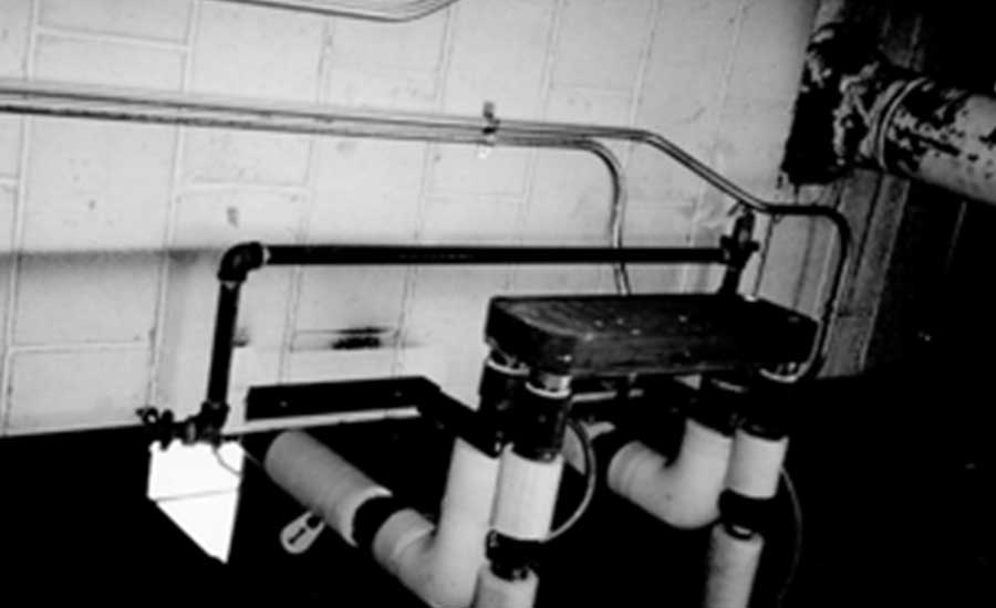
The district heating hot water pipe was brought underground to the existing mechanical room. A heat exchanger was installed to isolate the district water from the building water (see Figure 2).
The following conversion methodology was used: A stamped steel panel radiator of the same heat capacity as the existing electric baseboard was installed in each room. Supply and return piping from the mechanical room was run through a utility chase to serve each floor. From this point, the front half of the building was served with hot water. Another pair of risers (supply and return) was located in the northwest corner of the building to serve the rear half of the building. These risers were run through apartments, where they were boxed in with sheetrock. Horizontal header runs were located above dropped ceilings in corridors.
The installation of the radiators and lines required just a few hours per apartment. Lines were surface-mounted and run under attractive wood grain plastic housings that resemble baseboard molding. Penetrations through walls were limited to two ¾-inch holes for the supply and return lines and are concealed by the housings. Each pair of lines feeds up to six apartments. The radiators have self-contained thermostatic controls that require no wiring.
Conversion of the heat source for domestic hot water and makeup air heating systems from gas to district heating hot water was also performed. The domestic water system used three storage tanks. The natural gas flame located under each tank was turned off. The existing recirculation pump was used to circulate cold tank water through a new external heat exchanger. This heat exchanger heats the domestic water to 120° using the district hot water as the new heat source. A hot water coil was included in a replacement makeup air unit. This coil provides the heat needed to raise the temperature of makeup air to the requisite level.
Supply and return piping for radiators on the front wall of the building was fed from the MER, through the first-floor dropped ceiling, and up the utility chase, located at the front left side of the building (just to the right of the front lobby). Supply and return piping for the upper three floors of the back of the building was fed from a riser that starts in the northeast corner of the mechanical room. It extended through the second and third-floor apartments and ended in the fourth-floor apartment. The lounge and recreation rooms on the first floor were fed from the MER with the pipes going through the tenant storage area. The above supply and return pipes as well as all new piping in the MER, and that which goes through the tenant storage area, were insulated with 1 inch of fiberglass insulation.
Each apartment has two radiators, one in the living room and the other in the bedroom. Each radiator has one thermostatic radiator valve and one balancing valve. Two-panel heights (300 and 550 mm) were used. The balance valves (preset) are tamper-proof and provide draining of the radiator while keeping the piping system closed off. The project required 81 radiators, thermostatic radiator valves, and balancing valves.
A specification was prepared, and bids from contractors with the following qualifications were obtained:
- Licensed as a plumbing contractor in New York;
- Compliance with applicable state and federal laws and regulations;
- Familiarity with district heating and retrofit work; and
- A record of satisfactory performance on similar work in the past five years.
The project was financed by a combination of a rebate from the local electric utility, with funds obtained from the Department of Housing and Urban Development (HUD). The electric utility has a demand-side management program for reducing the demand for electrical power. The goal of this program is to avoid the increased costs associated with providing new sources of power and the increases in peak demand that entails following an increase in distribution facilities. An inspection of the building’s electric records has indicated the peak demand for electrical power would be reduced by 183 kW. The cost estimate was used to calculate a simple payback period. Once it was determined this payback was under maximum HUD requirements, the remaining funds were obtained from HUD.
The heat source for the hot water loops is the district heating system operated by the Jamestown Board of Public Utilities. The utility welcomed both the reduction in electrical demand and the increased load for the district heating system. The obstacles to the conversion were minimized by the cooperative attitude on the part of the utility, including the subsidy for electric power demand reduction. This enabled the project to be implemented, and the crucial data on hot water heating installation cost, schedule, and subsequent performance to be gathered.
The actual conversion was performed over the period from three months. The analysis indicated the annual energy cost savings resulting from the conversion were 21%. The results of the life cycle analysis demonstrated the implemented project has an internal rate of return of 18% and a payback period of just under nine years.
Covenant Manor Building
The building is a brick-faced structure with a flat roof. The basement has a partially finished and heated tenant storage area. There is a mezzanine above the first floor, which has office space for the retail area. The second through eighth floors contain apartments. There are a total of 88 apartments. There are two two-bedroom apartments, which are located on the second floor. The other 86 apartments are one-bedroom units. Each apartment is approximately 700 square feet. Each apartment had electric fin-tube baseboard radiators that cover the entire outside wall. They were controlled by a separate wall-mounted thermostat in each living room and bedroom. The kitchens and bathrooms have a fan coil unit recessed into the wall with a built-in thermostat. The kitchen has a smaller output heater than the room size would normally dictate due to the heat released from the refrigerator. The total installed heating capacity of all 88 apartments was 529 kW.
Because each apartment has an exhaust fan in the kitchen and bathroom, a makeup air unit is necessary to offset this high loss of air throughout the building. The makeup air unit is located on the roof. It is rated for 14,000 cfm of outside air and heated the air using an electric coil rated for 356 kW. The fan in this unit ran around the clock, all yearlong. By providing heated makeup air in the heating season, the unit reduces the amount of cold air leaking into the building, which would otherwise occur when exhaust fans are operated and exterior doors are opened.
The heat source for the hot water supply was the district heating system. Covenant Manor is located 250 feet from the nearest district heating piping, as it existed prior to the conversion. However, the building is located between two sections of existing underground district heating pipe the district heating company desired to interconnect. Therefore, the cost of running the piping to the Covenant Manor was borne by the district heating company and was not an additional expense to the customer.
The connection to the district heating system is similar to the Anderson Towers. The district heating hot water pipes were brought underground to the existing mechanical room located in the northwest corner of the building. A heat exchanger was installed to isolate the district water from the building water.
The following conversion methodology was used: A stamped steel panel radiator of the same heat capacity as the existing electric baseboard was installed in each room. Piping from the mechanical room was run through the basement to four pairs of risers. These risers were installed at stairwells with Sheetrock enclosures in corridors and apartments. These risers feed lines on each floor that service the apartments. Up to nine apartments in a row are served with hot water from each pair of supply and return lines. Piping in apartments is run along walls and covered with standard baseboard enclosures. These enclosures can accommodate larger lines, which allow fewer risers to be used to feed each floor.
The roof-mounted makeup air unit was found to be in poor condition, and the entire unit, including the electric heater, was replaced. The air heating is now performed by a new hot water coil located in the replacement makeup air unit.
An additional effort addressed conversion of the heat source for domestic hot water from gas to district heating hot water. The domestic water continues to use the pre-existing tank for storage. The existing heater was bypassed, and a new pump is used to circulate cold tank water through a new external heat exchanger. This heat exchanger heats the domestic water to 120° using the district hot water as the new heat source.
Each apartment room has a panel radiator installed in place of the existing electric baseboard. Each radiator is equipped with a thermostatic radiator valve and a balancing valve.
The piping under the radiator is covered with skirting. The balance valves were preset, tamper-proof, and provide draining of the radiator while keeping the piping system closed off. The project required 268 radiators at 450-mm equipped with thermostatic radiator valves and balancing valves. The bathrooms have windowsills at 38 inches above the floor, so the taller 550-mm radiators were used.
A hot water coil was installed in the ductwork in place of the existing unit. It has a static pressure drop no greater than ¼-inch Hg across the coil. The old electric unit above the roof was removed and disposed. A hot water unit heater was installed in the elevator penthouse with the same rating as the existing electric unit. The fan shall come on based on a thermostat.
The project was financed by a combination of a rebate from the local electric utility and HUD. The results of the life cycle analysis demonstrated the implemented project has an internal rate of return of 11.4% and a payback period of 12 years.
Jamestown High-Rise Building
The building was built using modular construction and has 101 apartments, 97 of which are one-bedroom units. Two units are two-bedroom apartments. Of the 97 one-bedroom apartments, 51 units are efficiency units. They have the same footprint as a one bedroom but without a partition wall between the bedroom and living room. Each room has an electric baseboard heater. Most of the kitchens and bathrooms are interior rooms and have no heating elements.
The proposed conversion methodology is essentially the same used for previously described buildings. In addition to the conversion of the individual space heating elements, this conversion addressed the transition of the heat source for DWH from electric to district heating hot water. The domestic water will utilize the same four tanks for storage. The electric heater coil is bypassed. A new pump is used to pump cold tank water through a new external heat exchanger. This will allow to heat up the domestic water to 120° using the hot district water as the new heat source. The project required 268 450-mm radiators. There is also a unit heater in the elevator penthouse and a hot water coil for the makeup air ductwork. The results of the life cycle analysis demonstrated the implemented project has an internal rate of return of 14% and a payback period of 10 years.
Potential for Conversion to a District Heat Pump System
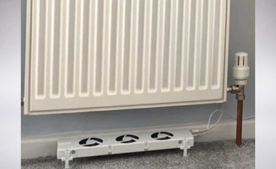
To increase efficiency of the described systems, designers considered replacing the district heat source with a ground-source heat pump (GSHP) with a potential COP of 3-5. According to the U.S. Department of Energy, GSHPs used for both heating and cooling can save up to 70% in energy costs. This will eliminate the use of associated fossil fuels at the district energy source and reduce the greenhouse gases (GHGs). The described above-flat radiators are well-suited for lower hot water supply temperatures. To increase the heat output of the flat radiators the use of ventilators (see Figure 3) can be considered3.
References
- Pedersen, E.K. at all. Physical Changes of Indoor Dust Caused by Hot Surface Contact. Atmospheric Environment, August 2001.
- Oliker, I. Case Study: District Heating Supply from a Combined Heat and Power Plant. Consulting Engineer, February 2021.
- Myhre, J.A. Potential of Ventilation Radiators. Royal Institute of Technology, Sweden, April 2011.


