
FIGURE 1. Server airflow and rack enclosure measuring point.
Controlling humidity in IT environments is essential to achieving high availability. This article explains how humidity affects equipment, and why humidity control is required. The author offers quantitative design guidelines for existing and new computing installations, and he also explains the hidden costs associ-ated with over-humidification.
Every piece of electronic equipment, data center, and person on earth is located at the bottom of an ocean of air. This fact is taken for granted to be a good thing, but there are instances when the air surrounding IT equipment can directly lead to its failure. The water vapor contained in air protects IT equipment from dangerous static electrical discharge.
Reliance on precision cooling solutions to maintain the proper humidity level in a computer room or data center does not always ensure proper humidity levels at the IT equipment air intake. Let’s look at the nature of humidity, its effects, and its management in computer rooms and data centers.
TABLE 1. Comparison of static electrical buildups at different rh levels.
Effects of humidity in the IT environment
Humidity in the computer room or data center provides beneficial effects when it is maintained at proper levels and potential problems when it is at a level that’s too high or too low. The primary benefit of maintaining proper humidity levels is a reduction in the “charging” effect that can lead to static electrical discharge by making the air itself just a little more electrically conductive and the surfaces it touches just slightly “wet.”Because of the air’s slight increase in conductivity, the imbalance of positive and negative charges that create static electricity are less likely to result in elec-trical discharges (10,000+ volt sparks) that can damage computing equipment.1 The low-humidity cooling air moving throughout the data center itself can be a source of static electricity every time it moves across an ungrounded insulated surface and must be guarded against by maintaining proper humidity levels. The effects of varied rh levels on everyday activities that generate static electricity are shown in Table 1.
The values of 250 and 1,500V seem high, but as static electricity are not real threats to computing equipment. The 12,000 and 35,000V values can discharge as sparks and can cause damage. High rh levels in the IT environment further reduce the chance of static discharge but are not desirable due to the increased likelihood of corrosion of metal components. High humidity levels can also increase the risk of water damage to equipment. This is why most IT equipment specifications show the acceptable humidity range in terms of non-condensing humidity. In essence, equipment manufactures are stating that their equipment will operate normally within a humidity range (typically 20% to 80% rh) as long as the temperature of the equipment itself and everything around it remains above the dewpoint.

TABLE 2. Humidity guidelines for IT equipment, computer rooms, and data centers.
Infiltration, condensation, and ventilation cause changes in IT environment humidity. Humidifiers (add water vapor) and dehumidifiers (remove water vapor) maintain IT environment humidity.
Infiltration.If we could place a high-humidity body of air next to a low-humidity body of air, the two would quickly equalize to a humidity level between the high and low levels. When computer rooms are at different humidity levels than the outdoor or office space air that surrounds them, the humidity levels con-stantly try to equalize between the spaces. Obviously, the walls, floor, and ceiling surrounding the IT environment should stop this equalization, but in many cases they do not. Water vapor can escape or enter through any porous surface or microscopic crack and change IT environment rh. The rate of humidity gain or loss due to infiltration is dependent upon the amount of open area and difference in humidity and temperature between the spaces.
For example, let’s assume a small data center (73°, 50% rh) was in a location where the outside weather was 35° and 30% rh. If we open a normal-sized door (an emergency exit door for example) between the room and the outdoor environment, the room’s rh would drop below 50% almost immediately. In less than 12 minutes, the room would be below the minimum recommended rh of 40% (assuming no supplemental humidification in the room). If the data center had supplemental humidification, we would lose 6.1 lb of water for each hour the door was left open. Infiltration problems require extra equipment to regulate humidity levels and in severe cases regulation may be impossible.
TABLE 3. Characteristics of humidifiers.
Pumps inside the cooling equipment transport condensate away from the IT environment and into the building drainage system. Humidifiers are used to add needed water vapor back into the airstream exiting the cooling equipment. Humidifiers are a very common option found in CRACs and CRAHs and are dis-cussed in the humidity control section of this article.
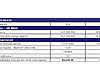
TABLE 4. Humidification cost savings example at lower setpoint.
IT equipment and environment humidity guidelines
Humidity guidelines for computing equipment are published by most equipment manufacturers. Guidelines for data centers and computer rooms are pub-lished by ASHRAE. Typical guidelines are provided in Table 2. Maximum dewpoint temperatures are provided to establish criteria to reduce the chances of condensing humidity, especially when the IT environment is subject to rapid temperature change.Humidity Measurement
The single most important place to maintain proper rh is at the cooling air intake opening on IT equipment. The acceptable temperature and humidity ranges for equipment published by IT manufacturers are based on readings at the point of air intake. Most pieces of computing equipment locate the cooling air intake in the front and the exit in the back as shown in Figure 1. Note the exhaust air exiting the server has a higher temperature and lower humidity but the dewpoint is unchanged. This is because the nature of the heat a server generates raises the temperature of the cooling air but does not change the amount of moisture in the air. The concept of using a single dewpoint setting for data center humidity control is discussed later in this paper.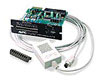
FIGURE 2. Typical air temperature and humidity measuring device.
Use a temperature-humidity probe that interfaces with currently used operating and control systems to monitor and provide proactive warning of out-of-range humidity conditions (Figure 2). There are also many hand-held monitoring devices available that allow for spot-checking of temperature and rh any-where in the room.Most CRACs and CRAHs measure the humidity level of data center air as it returns into the unit from the IT environment. Figure 3 shows the monitoring points on a down-flow unit. This data is used to control the operation of humidifiers if they are installed within the unit. The standard user interface on most precision cooling units provides readout of the rh when requested.
Humidity Control
The best way to control humidity in the IT environment is to minimize the things that cause humidity levels to change and maximize the performance of the systems designed to regulate humidity.Minimizing factors external to the IT environment that affect humidity.Minimizing infiltration protects the IT environment from chronic humidity control prob-lems that become acute with significant changes in outside weather. Use vapor barriers in the construction or renovation of computer rooms and data centers to control infiltration. A vapor barrier is a special non-porous sheet, paint, caulk, or other construction material applied to the walls, ceiling, and floor of the room that water vapor cannot penetrate. It surrounds the IT environment and minimizes humidity gain or loss from outside the room.
There are often fewer people working in data centers than in normal office space. For this reason, the quantity of outside air used for ventilation purposes is usually small and should be planned for by cooling professionals when designing the room. Office space that is converted into a computer room and still retains the building air conditioning system for ventilation purposes creates unique challenges and benefits. The benefit is that the outdoor air required for ventilation is already processed by the building climate control system to a moderate temperature and humidity level before it enters the computer room.
The challenge is ensuring the large volume of air building climate control systems typically introduce into office space (now converted to a computer room) does not conflict with the operation of the room’s additional precision cooling equipment. For example, if the volume of air entering the room from the build-ing ventilation system is warmer or at a different rh than the desired setting on the CRAC, a portion of the air conditioner’s capacity will be used to cool or change the humidity of the air as necessary.
Computer rooms with temperature and humidity problems that utilize both building and precision cooling systems require detailed analysis to diagnose and optimize.
Minimizing factors internal to the IT environment that affect humidity. Humidifiers exist in virtually all data centers and in some cases are almost continuously used. They are a commonly installed in precision cooling systems but may also be standalone central systems. Humidifiers installed inside CRACs replace water lost to condensation before the air exits the cooling unit. Water vapor supplied by central humidification systems has to migrate across the IT environ-ment. This equalization process happens quickly, and in most cases the cooling air is acceptably humidified prior to its entry into the IT equipment.
In environments with limited hot/cold air mixing or fully ducted air supply or return systems, condensation within cooling units is very limited or eliminated all together. In this case, humidifiers in the individual cooling units can be minimized or eliminated resulting in lower capital, operation, and maintenance costs. Proper air management practices favor the use of central humidification.There are three types of humidification systems commonly installed in CRACs and CRAHs.
- Steam canister humidifiers introduce liquid water into a canister containing electrodes. When the electrodes are powered, water is boiled and steam (water vapor) is produced. The steam is introduced via a tube into the airstream to be humidified.
- Infrared humidifiers suspend quartz lamps over an open pool of water. The effect of the intense infrared light on the surface of the water is the release of water vapor that migrates into the airstream requiring humidification.
- Ultrasonic humidifiers rapidly vibrate water to create a fog or mist that is introduced into the airstream requiring humidification.All three designs effectively humidify the IT environment. Steam-canister and infrared humidifiers use more electrical energy than ultrasonic humidifiers. Ultrasonic humidifiers are more expensive to buy because they require an RO water purification system to supply water (smaller systems can sometimes use de-ionized water).
All three types of systems require maintenance. Steam canisters must be cleaned or replaced and infrared systems require cleaning and bulb replacement. Ultrasonic systems require transducer replacement, and their associated RO water purification systems require significant maintenance. Impurities in the water used in an ultrasonic system can be deposited into the computer equipment itself if proper procedures are not followed.
The latest steam canister designs have the capability to regulate the amount of steam they produce to the exact amount needed and also have the ability to compensate for electrode fouling. This results in better humidity control, less electrical consumption, and fewer maintenance requirements. A summary of the relative costs associ-ated with the three types of humidifiers is shown in Table 3.
Two factors affecting the amount of water a cooling system removes are the temperature of the air returning to the cooling system and the engineering of the cooling system itself. Air management practices must minimize the mixing of hot and cold air within the IT environment and guard against cooling air bypassing IT equipment all together. When previously cooled bypass air re-enters a CRAC or CRAH, it’s cooled to a lower temperature than is desirable. This means the air progressively loses more water vapor to excess condensation as it repeatedly passes through the cooling coil. It’s an extremely undesirable situation for several reasons:
- The unit uses a larger portion of its available cooling capacity to remove extra water when that capacity could otherwise be used to cool computer equip-ment.
- Humidifiers are also forced to operate at full capacity, wasting electricity.
- Cool air bypassed back into the CRAC or CRAHs can “trick” the unit into reducing its cooling capability because it senses that the room’s cooling needs are met.
All these effects waste energy and risk thermal damage to computer equipment due to a lack of cooling airflow. In this situation, lowering the air conditioner’s temperature setpoint will have no effect on room temperature and may even increase the rate of condensation at the cooling coil. This costly and potentially damaging sequence of events is all too common and can be avoided by proper air management practices in the IT environment.
The engineering of a precision cooling unit itself also determines the amount of condensation occurring during normal operation. The amount of moisture removed by the air conditioner is dependent on the size of its cooling coil, the cooling coil temperature, and the velocity at which air is forced through it. A measure of a precision cooling unit’s capability to remove heat without removing moisture is the unit’s sensible heat ratio. A value of “1” indicates no mois-ture is removed from the air via condensation. This number (or the information to calculate it) is published in the manufacturer’s technical data for their cooling systems. It’s an important indicator of the efficiency of the cooling system and is usually considered in the specification process. Sensible heat ratio values closest to “1” are best for IT environments.
CRACs are also capable of increasing their rate of condensation to purposely dehumidify the IT environment. This is achieved by lowering the cooling coil temperature, slowing the airflow through the cooling coil, or reducing the amount of the cooling coil the same amount of refrigerant is introduced into. The air exiting the cooling coil under these conditions is colder than normal and has lost more moisture to condensation.
The air is further dehumidified by the addition of reheat. CRACs use additional coils (if installed) heated by electricity, steam, hot water, or hot gas (hot re-frigerant from the compressor) to reheat the exiting air stream back to the normal exit temperature. Some systems assist the reheat process by mixing smaller amounts of warm air from the IT environment with the cold dehumidified air before it exits the precision cooling system.
In most climates, dedicated dehumidification happens only occasionally and is often associated with periods of rainy weather. Frequent or continuous dedi-cated dehumidification is usually the result of severe infiltration (in humid climates) or over-humidification occurring in another CRAC in the room.
Dewpoint control of IT environment humidity
Controlling IT environment humidity by maintaining dewpoint temperature is more cost-effective than maintaining rh. As air increases in temperature, it requires more moisture be added to maintain the same rh. For example, air at 90° and 50% rh contains 96% more water (by weight) than air at 70° and 50% rh (at sea level). If the air returning to two CRAC units (with the same rh setting) in the same room is at different temperatures, the higher temperature return air will have more water added to it by the humidifier in the CRAC unit than the lower temperature return air will. When a room contains several CRACs set to maintain the same rh, the unequal addition of moisture among them can eventually trigger one or more of the units to go into dehumidification mode. The other air conditioners will detect the resulting drop in humidity and will increase their own humidification to compensate.
FIGURE 3. Cooling system return air humidity monitoring.
Dewpoint control of IT environment humidity greatly reduces the frequency of demand fighting. This is due to the fact that as air increases in temperature in an IT environment, its dewpoint stays the same. For example, air at 90° exiting a piece of computer equipment has exactly the same dewpoint as the 70° air entering the computer. Rh and measured air temperature are always related for any specific dewpoint temperature.
When several CRACs or CRAHs are set to maintain humidity via dew point, large differences in return air temperature will not drive excessive humidifica-tion or dehumidification in different units. All cooling units simply maintain humidity based on the actual amount of water required in each pound of air that passes through the unit. Elimination of demand fighting in data centers has increased the efficiency of the cooling system by up to 30%.
Real-World Examples of Cost Minimization
Setting humidity higher than actually required by IT equipment lowers the heat removal capability of the unit and wastes electrical energy. Humidifiers must add unnecessary water to the air flowing through the CRAC or CRAH unit. This can waste thousands of gallons of water per year in a typical data center.Furthermore, steam-canister and infrared humidifiers are significant sources of heat that must also be removed by the CRAC and consequently further de-tracts from its capacity. This situation is made even worse when significant hot and cold air mixing occurs in the data center because the lower temperature air returning to the CRAC unit looses more moisture in the cooling process than warmer, unmixed air would. Therefore, it is essential not to operate a data center at higher humidity levels than the minimum recommended level.
Some data centers have high velocity paper or forms printers. These printers can generate significant static electrical charge. To control static discharge, rh levels of about 50% or higher are sometimes specified. However, for data centers without large high-speed forms printers, an rh of 40% will control static charge. Operating a data center at 40% minimum rh instead of 45% or 50% can save significant amounts of water and energy. Operation of the system within lower limits of the rh design parameters should be considered for efficiency and cost savings. A slight change in setpoint toward the lower end of the recommended range can have a dramatic effect on the heat removal capacity and reduction in humidifier run time.
In Table 4, an analysis of a single glycol-cooled CRAC with 50kW of IT equipment heat removal capacity was conducted. This example supports the assumption that proper construction techniques that minimize humidity infiltration combined with proper air and humidity management practices can amount to significant reductions in operating capital. The 49° column in Figure 4 shows the entire capacity of the CRAC being devoted to cooling IT equipment. No moisture is being unnecessarily removed from the air, so no moisture has to be added back in. This configuration simultaneously provides the IT and facilities professional with maximum heat removal from IT equipment and minimum operational cost.
Conclusion
The amount of moisture contained in the air used to cool IT equipment can help ensure its availability or lead directly to its failure. There is an interdependent relationship between humidity management and cooling air management procedures. Dehumidification of air always reduces IT heat removal capability. Humidification of air always costs money. Both should be used only when absolutely necessary. Effective humidity control in the IT environment is most effec-tively applied as part of an overall IT environment strategy involving optimization of air management, IT load planning, and infiltration minimization.ESEndnotes
1. The assertion that reduced static electrical charging occurs as rh rises is being challenged by recent research. This research concludes that the same amount of charging occurs under all conditions, and its the insulating layer of water molecules that forms on surfaces as rh increases keeps static electrical discharges from occurring. This does not support the data shown in Table 1.However, in each case its agreed that increased moisture content in air restricts static electrical dis-charge.Assumptions and specifications for Table 4Both scenarios in the humidification cost savings example in Table 2 are based on the following assumptions:
- 50 kW of electrical IT loads, which results in approximately 50 kW of heat dissipation
- Air temperature returning to CRAC inlet is 72°F (22.2°C)
- Based on 1-yr operation (24/7) which equates to 8,760 hours
- CRAC unit volumetric flow of 9,000 cfm (4,245 L/s)
- Ventilation is required but for simplification it was assumed that the data center is completely sealed - no infiltration / ventilation
- Cost/kWh was assumed to be $0.08 (U.S.)
- Standard downflow
- Glycol cooled unit (no multi-cool or economizer)
- Electrode steam generating humidifier (Plastic canister type with automatic water level adjustment based on water conductivity)
- Humidifier capacity is 10 lb/hr.
