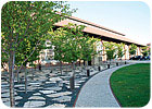
FIGURE 1. A 10,000-point BAS connects the buildings at the Urban Outfitters headquarters
campus in Philadelphia.
campus in Philadelphia.
HVAC systems in Urban Outfitters’ new headquarters had to work not only for comfort but also as part of the interior design. Ultimately, radiant heating and cooling, CFD to navigate some tight spacing, and some value engineering touches created a configuration every bit as distinctive as the facility’s koi ponds and gourmet cafeteria.
When Urban Outfitters, Inc., decided to establish its new headquarters at the Philadelphia Navy Yard, the retailer sought a distinctive approach to the adaptive reuse of several former shipyard workshop buildings to serve as offices, design studios, and support space for more than 500 staff members.
The company, which markets clothing and home accessories to young men and women under the Urban Outfitters, Anthropologie, and Free People brands, is known for its creative store designs and product displays, which blend modern industrial fixtures with found objects. So it is not surprising that that the owner and its architect, Meyer, Scherer & Rockcastle, Ltd. (MS&R), envisioned the central chiller plant for the 280,000-sq-ft project as a functional sculpture that would be viewed by employees and visitors through a floor-to-ceiling glass curtainwall.
Under the terms of nine contracts for Blue Rock Construction, Inc., Fluidics provided preliminary project budgeting and value engineering services; construction and installation of a new, 1,710-ton central chiller plant, boilers, and mechanical piping for the emergency generator in the main building; new HVAC and plumbing in the main building and two other renovated buildings; and a new underground distribution system to connect the central plant to four renovated buildings.
Fluidics also installed a radiant heating and cooling system under the floor of the central core of the main building, designed to ensure employee comfort and an attractive environment. One of the contracts called for installation of a 10,000-point BAS interconnecting all buildings using the customer’s IT network. The mechanical system was designed by PHY, Inc., Consulting Engineers.

FIGURE 2. The central core of the main building. The system provide 115° water in the heating
season and 52° water in the cooling seasons.
season and 52° water in the cooling seasons.
In One-Third The Time
Fluidics provided preliminary project budgeting and value engineering services in fall 2005. Construction/installation got underway in January 2006; the central plant was operational by July, employee occupancy was complete by November, and the project was completed and commissioned by December 2006. The job was completed on schedule - in approximately one-third the time that would normally be allotted to a project of this scope - and with zero lost-time injuries. Moreover, Fluidicsí prudent value engineering saved the owner approximately $300,000.The 1.5-million-sq-ft headquarters site is part of a National Register of Historic Places District of the former Philadelphia Naval Operations Center, which was decommissioned as a Navy base in 1996 and is in the process of conversion to commercial and other uses under a master plan of the City of Philadelphia and the Philadelphia Industrial Development Corporation (PIDC). Altogether, the Navy Yard is a 1,200-acre development located along seven miles of waterfront on the east side of Philadelphia at the confluence of the Schuylkill and Delaware rivers. According to PIDC, the master plan builds on the 4-million-sq-ft of existing activity and the 6,000 employees already located on site.
Front and Center
The main building houses the central plant, which comprises three Trane centrifugal chillers and associated equipment, a Baltimore AirCoil two-cell cooling tower, Aurora split case pumps, Alfa Laval plate heat exchangers, as well as control valves, large-bore piping, and accessories - providing 1,710 tons of cooling capacity. The central plant also houses three Bryan combination gas/oil-fired boilers and an emergency generator.The system is designed to circulate chilled water at an average temperature of 38°F through a high-velocity pumping system, which enabled selection of smaller-diameter piping (e.g., 3 to 4 in. rather than 5 to 6 in.) throughout the project, reducing the costs of materials and labor. Hot-water temperature resets from 200° down according to outside air temperature.
The building contains a gourmet cafeteria for employees (open to the public), expansive fern and bamboo gardens, two large koi ponds, and a space for quiet contemplation. Exercise facilities were located over the chiller plant, which is visible from the ground floor of the building through the glass curtainwall.
Overcoming Installation Challenges
Every central plant installation project poses challenges, including the coordination issues associated with major equipment, large-bore piping, and associated fittings and valves. In this case, the aesthetics of the chiller plant were among the ownerís key considerations. To ensure that the owner’s goals were achieved, Fluidics developed 3-D CAD drawings for review by the owner and design team; in turn, the engineer used the CAD drawings to create a reduced-scale model of the chiller plant. Layout changes were incorporated based on design reviews of the drawings and model, as well as weekly walk-through inspections by the owner’s team.The three chillers are located front and center in the final layout of the chiller plant, with pumps to the left and right, and heat exchangers and accessories in the rear (the boiler room is located behind a solid wall at the rear of the chiller plant). Because the front wall was glass and the rear wall was intended for a decorative mural, wall space that is normally used to mount equipment, including electrical panels, starters, VFD controls and monitors, was reduced by half. The CAD department’s thoughtful layouts provided both the aesthetic and practical solutions to this challenge, including maintenance of required clearances in front of mounted equipment. In addition, the installation team made sure that all the hangers, and the spring boxes supporting them, were appropriately spaced and facing the same direction.
All of this was accomplished on a tight schedule within an even tighter space. The high bay area, at 60 ft high, 300 ft long, and 90 ft wide, was jammed with 30 to 40 platform lifts of various types and numerous trades people, including steamfitters, plumbers, sheet metal workers, insulators, iron workers, steel workers, glazers, electricians and painters, all working at once.
Unique Radiant System
Fluidics also installed a unique radiant heating and cooling system under the floor of the central core of the main building. It involved over 25,000 ft of plastic tubing, the installation of which had to be sequenced with the installation of the stone, rebar and wire mesh; pressure tested; and closely monitored during each concrete pour to ensure no damage was caused during the concrete pours. The system was fed from nine manifolds controlled by three averaging sensors in the slab, operating at 115° water in the heating season and 52° water in the cooling season. The conditioning of the slab in this manner is designed to complement the building HVAC systems for both comfort and energy efficiency. Most radiant underfloor systems address heating, but this was the first dual-temp system in our experience.High Tides and Cold Weather
Another key challenge was met in the installation of the exterior underground piping under the direction of the PIDC. Compounding the normal challenges associated with installing and welding piping in a confined trench space, the work was impacted by high tides and winter’s cold.As the site was over 100 yrs old, the crew encountered surprises such as existing underground utilities and bulkheads. After excavation and soil testing, Blue Rock laid stone to elevate the piping above the mean high water line. Nevertheless, during rain events and extreme high tides, water did flow into some areas of the trenches, which had to be continually pumped during the installation process. The crew was properly attired and constantly monitored to ensure safety.
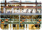
FIGURE 3. The central plant, located behind a glass curtainwall in the main building, acts
as a functional sculpture.
as a functional sculpture.
Form and Function
New HVAC systems and associated plumbing were designed to function efficiently and ensure occupant comfort in the largely open floor plans of three other buildings. One was heated and cooled with a combination of two Trane rooftop multizone units, two interior multizone AHUs, and 350 linear ft of perimeter baseboard heating element. Another building was heated and cooled with five interior multizone AHUs and 400 linear of perimeter baseboard heating element. The owner wanted fintube radiation enclosures with a highly perforated industrial look, so Fluidics had these custom-designed by the manufacturer, Vulcan Radiator Company, to balance form and function.Both the lengths of each of these old industrial buildings, at approximately 300 ft, and aesthetic considerations drove the installation of system components. Like the equipment in the central chiller plant, the air distribution ductwork was designed to be visible to building occupants, so Fluidics submitted all shop drawings for approval by the architect and owner. In some cases, ductwork had to follow the interior roofline; in others, it had to be positioned so it passed through existing steel trusses.
Energy Management
Management and monitoring of the three buildings, 15 HVAC systems, and their 4,500 control points is accomplished with a Honeywell EMS with complete on-screen graphic status display of each piece of equipment in each building. The EMS is accessed both locally and remote via the internet with automatic Alpha numerical paging and e-mail notification in the event of a critical alarm condition.Value Engineering
Judicious value engineering saved several hundred thousand dollars while ensuring that the HVAC systems met performance specifications. For example, in the main building, the top of the center bay was approximately 60 ft above the finished floor. Each side of this high bay and each end of the building had large expanses of glass, as did a second, lower roof. PHY, Inc.’s design called for fin-tube radiation beneath all the glass to prevent condensation, but Fluidics recommended that they delete it on the basis that the natural effect of rising heat in the high bay area would prevent condensation. The experiences of the first cooling and heating seasons proved this recommendation to be valid. This alone saved the owner approximately $100,000 in capital dollars.The design also called for roof ductwork to be both lined and insulated, but a value engineering analysis led to the recommendation to eliminate the insulation and use lined, weatherproof ductwork. This resulted in a cost savings without impacting performance.
The project received a 2007 Award of Excellence by The Urban Land Institute, a prestigious award given to only 10 developments in North America. HVAC systems in Urban Outfitters’ headquarters at Philadelphia Navy Yard are not only designed for comfort and efficiency, they are also fit to be seen thanks to a thoughtful team approach to the installation.ES
