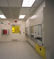
To strengthen Oklahoma's infrastructure for high-tech research, the CLPR has sponsored construction of the first multidisciplinary cleanroom facility for materials synthesis, processing, device fabrication, and testing in the state. The facility includes Class 100 (M3.5), Class 10,000 (M5.5), and Class 100,000 (M6.5) cleanrooms for semiconductor processing and device fabrication, including photolithographic tools and a metal-organic chemical vapor deposition reactor for advanced semiconductor thin film growth. The 6,000-sq-ft facility comprises clean spaces, personnel and material airlocks, a conventional analytical laboratory area, and mechanical and electrical support spaces.
Industry Standards
Containing noxious fumes in a laboratory is accomplished in a fume hood. The American Society for Heating, Refrigerating and Air-Conditioning Engineers (ASHRAE) Standard 110-95, "Method of Testing Performance of Laboratory Fume Hoods," defines test methods to ensure that a fume hood is installed and operating properly.The current test is comprised of three parts: flow visualization, face velocity measurement, and tracer gas containment. Flow visualization is accomplished by introducing smoke into various portions of the hood and observing the hood's ability to contain the smoke. Face velocity measurements confirm the hood's ability to provide a consistent air velocity across its face. Tracer gas containment confirms the hood's ability to contain gases under static (hood sash stationary) and dynamic (hood sash movement) conditions.
To ensure that exhaust stacks are operating properly, stack design is addressed in American National Standard Institute (ANSI) and the American Industrial Hygiene Association's (AIHA's) Standard ANSI/AIHA Z9.5, "Laboratory Ventilation." It states that exhaust gases be discharged vertically up from a minimum of 10 ft above the adjacent roof line, at an exit velocity of 3,000 ft/min.
Because of the nature of semiconductor manufacturing, chemicals new to the air on campus were introduced, and that attracted the attention of campus safety officials. Arlene Lanman, project manager for Oklahoma State University, was well aware of the need to meet applicable standards to ensure safety.
"From the outset of design, we knew we needed to address the containment, capture, and nonre-entrainment of the several health hazards associated with silicon chip development for specialty applications," said Lanman. "To this end, we worked in concert with the design engineer to identify and implement strict design standards including ANSI/AIHA Z9.5, NFPA 318, and numerous SEMI Recommended Standards. Just as important, we established field testing procedures to help ensure compliance."
Temporary Cleanroom, Permanent Lessons
To allow research to begin, a temporary Class 100,000 cleanroom was built while the permanent facility was constructed. A fume hood was installed within the temporary cleanroom and tested per ASHRAE 110-95.The ASHRAE test uncovered deficiencies in the design of the exhaust stack that could result in contamination of the outside air intake.
The first part of the test involved smoking the fume hood to visualize flow patterns, hood capture, and containment ability. The hood performed well and contained smoke. Next, a grid was laid out on the hood face and air velocities were measured at the grid centers. This portion of the test confirmed that the hood installation was appropriate, and grid velocities were consistent within the design parameters and test variance allowance.
With the first two parts of the ASHRAE test completed, the hood and its installation passed as acceptable and would have been approved under the old ASHRAE standards. However, when the third part of the test, which was adopted in 1995, was performed, problems became apparent.
In this part of the test, a mannequin was placed in front of the fume hood and a gas sensor placed at its mouth. With the hood operating, a test gas, sulfur hexafluoride (SF6), was introduced into the hood and the amount of gas registered at the sensor recorded. Test gas discharge points were located at the left, center, and right front of the fume hood. At each location, the sash position was changed to simulate real world, dynamic conditions.
To test the temporary cleanroom fume hood, test apparatus was set up to establish a room background SF6 level. As the test progressed, the SF6 level continued to increase. Two possible explanations were explored: lack of hood containment, or contamination of the outside air intake by the exhaust system.
Hood containment failure, while possible, seemed less likely. For one thing, the hood had passed the first two portions of the ASHRAE test. For another, the testing agent's experience indicated that an upward trend in SF6 is usually the result of exhaust gases being recirculated into the room.

Outside Air Contamination Explored
To explore the possibility of outside air contamination, the gas sensor was moved to the support area for the temporary cleanroom. The support area is served by the same 100%-outside air unit. The sensor was located at the room air inlet, where SF6 levels were recorded as rising. The test indicated that the outside air intake was being contaminated by the exhaust system.This finding was further confirmed by visual inspection of the system when the hood was smoked a second time. The exhaust stack termination was located about 3 ft above the roof line, midpoint north to south, in an area of the roof that was 100 ft wide. It was located directly south of the grade-level air-handling unit.
On test day, the wind was out of the south. When smoke was introduced into the hood, it exited the discharge stack, ran north along the roof surface, and fell to the ground at the outside air intake as indicated in Figure 1. The exhaust stack was later modified to direct air up at a high velocity, with no recurrence of the episode.
This discovery reinforced the importance of separating exhaust points from outside air intake points, considering prevailing wind conditions when locating those points, and designing exhaust stacks to direct air up at a (predetermined) minimum velocity.
Permanent CleanRoom Design Requirements Established
The introduction of the new chemicals and their associated hazards onto the campus, coupled with the performance deficiencies uncovered during testing of the temporary cleanroom exhaust system, resulted in a critical review of the design of the exhaust system for the permanent facility.By using ANSI standards, good engineering practice, and compliance testing procedures, the following design requirements were established:
- Exhaust discharge point at least 10 ft above adjacent roof lines.
- Minimum exhaust discharge velocity of 3,000 fpm.
- Minimum outside air intake to exhaust point separation of 100 ft.
- Outside air intake located upstream of exhaust point when considering local prevailing wind conditions.

Design Solutions for Permanent CleanRoom
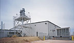
To meet these requirements, three solutions were decided upon: exhaust fans were located outdoors on a tower with the fan discharge point 10 ft higher than any portion of the roof; discharge velocity was more than 3,000 fpm; and the outside air intake was located more than 100 ft west of the exhaust stack. Figure 2 indicates the arrangement and shows the exhaust location downstream of the prevailing southwest to northeast wind direction.The exhaust fans were mounted with the discharge point 10 ft above the adjacent roof as shown in Photo 1. Because the roof structure was not capable of supporting the fans, a dedicated fan tower was constructed.
To confirm that these solutions would reduce re-entrainment, a two-dimensional model was developed using the method outlined in the ASHRAE Fundamentals Handbook. The model relates wind speed and direction, building geometry, and exhaust and intake locations to calculate various regions around the building skin. It is critical that the exhaust plume does not cross into either the roof recirculation or building wake recirculation regions. Using local weather data and the project drawings, the model was used to determine the various recirculation zones and the likely plume dispersion.
Multiple outside air intakes complicated the analysis. The study incorporated multiple wind directions to ensure the plume was likely to disperse before contaminating any of these intakes. The model confirmed that the exhaust stack arrangement resulted in good exhaust stream dispersion and no re-entrainment potential under expected weather conditions.
Summary
Using industry standards and recommendations during design resulted in a safe, functional research facility for the Center for Laser and Photonics Research at Oklahoma State University. The permanent cleanroom has been certified, and the fume hoods have passed ASHRAE testing. The CLPR staff has installed its equipment and research is under way."Although the university has installed multipoint toxic gas monitors, we have not experienced [the need for] detection," Lanman noted. "We attribute this success to having instigated strict design standards for capture and prevention of re-entrainment, and by conducting compliance testing during project execution." ES
