
One of the key aspects of a hydronic mechanical system is the pump. If the pump isn’t designed or selected correctly, the entire system will not function. Using general principles and rules of thumb to design a pump may work earlier on in design. However, thoroughly understanding how a pump is intended to operate within a hydronic system will help bring an efficient working design to fruition.
When it comes to selecting and designing pumps, two of the most crucial elements an engineer needs to understand are the pump curve and how the pump is controlled.
To understand how a pump is going to be controlled, one first needs to understand the pump curve. Pump curves provide a basis for selecting a pump that has the best chance of operating efficiently within a system’s design conditions. The curve describes the pump relationship between total head (feet) vs flow (gpm). This is then overlaid with a system curve, with the intersection of the two determining the pump operating point. It is crucial to select a pump with the intersection of the two curves at or near the best efficiency point (BEP), which is defined as “the flow at which the pump operates at the highest efficiency for a given impeller diameter and represented as a point on a pump curve plotting rate of flow and head for a significant period is ideal but often not carried out.”
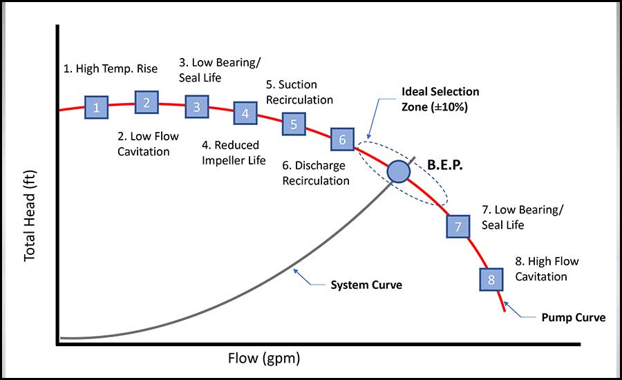
Selecting a pump outside of the BEP will most likely create a risk of cavitation, vibration, impeller damage, and reduced bearing and seal life (see Figure 1). Cavitation is a phenomenon that occurs when pockets of air enter the impeller and implode due the change in pressure. The collapse of the air pockets creates a great force that can cause catastrophic damage to the pump. Avoiding this early in the design by understanding where a pump needs to operate on the pump curve can save time and money later on in construction.
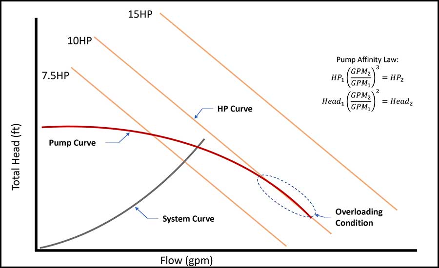
Another aspect of the pump curve to be aware of is if the selected pump will be overloading or non-overloading. In addition to the curves described above, pump curves generally overlay horsepower and impeller curves, derived from pump affinity laws, to indicate the size and power of the pump required at different operating conditions (Figure 2).
Selecting a pump outside of the BEP will most likely create a risk of cavitation, vibration, impeller damage, and reduced bearing and seal life (see Figure 1). Cavitation is a phenomenon that occurs when pockets of air enter the impeller and implode due the change in pressure. The collapse of the air pockets creates a great force that can cause catastrophic damage to the pump. Avoiding this early in the design by understanding where a pump needs to operate on the pump curve can save time and money later on in construction.
Another aspect of the pump curve to be aware of is if the selected pump will be overloading or non-overloading. In addition to the curves described above, pump curves generally overlay horsepower and impeller curves, derived from pump affinity laws, to indicate the size and power of the pump required at different operating conditions (Figure 2).
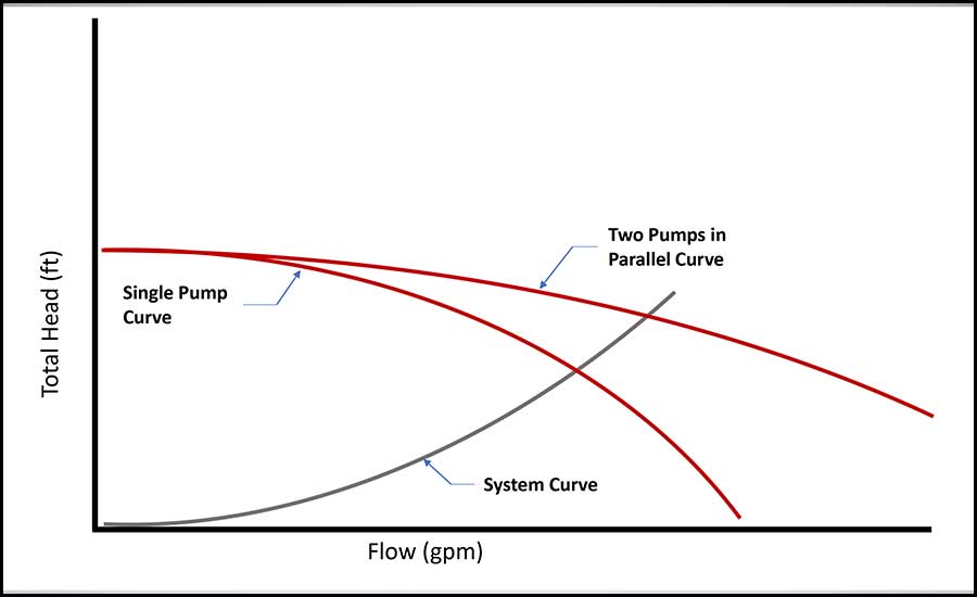
These previous examples have all been for one pump operation. If the engineer intends for multiple pumps to be operating in parallel at one time, then the parallel operation pump curve must be considered (see Figure 4). The curves should be analyzed at every pump combination scenario to ensure that the risk of cavitation is mitigated. Whether a single pump operates at a lower flow or multiple pumps operate at a higher flow, the design system curve should intersect the pump curves near the BEP.
The methods described above for selecting a pump on the pump curve is straightforward for a pump intending to operate at constant flow. However, the engineer can also apply these methods to variable flow pumps at the design operating conditions, given the engineer also considers the minimum flow requirements for the pump. Certain pieces of equipment served by the pumps, such as condensing boilers, allow the minimum flow rate requirement to be very low. The engineer should be aware of taking the larger of the minimum flow through these pieces of equipment or the minimum flow required for the pumps to avoid low flow cavitation.
After selecting a pump on the pump curve, it is important for an engineer to have a thorough understanding of how the pump is to be controlled. Pumps typically are provided with variable frequency drives (VFDs), which modulate the speed that the pump operates at based on what the pump is controlling. When the speed of the pump is altered, so is the pump curve, allowing the pump to produce a variety of flow and head conditions with mitigating the risk of cavitation (see Figure 5).


 air distribution systems")

