


HVAC system designers are faced with unique challenges when attempting to design energy-efficient HVAC systems. Code-driven energy efficiency requirements, owner’s project requirements (OPR), the latest HVAC analytics software, LEED project goals, chilled or hot water plant controls optimization packages, and manufacturer-driven cooling and heating technologies are all factors a designer must consider.
From a code perspective, and as it relates to water-chilling packages that are water-cooled, electrically operated, and centrifugal-type with a capacity larger than 600 tons, the 2018 version of the International Energy Conservation Code (IECC) has kept the same requirements as stated in the 2015 version of the code. Even though it’s not uncommon for a designer to receive water-cooled centrifugal chiller selections from manufacturers that boast an IPLV at or slightly above 0.3, from an energy performance perspective, we can only ask so much from water-cooled chillers that are provided with centrifugal compressors.
In general, HVAC analytics software platforms represent an extra layer of complexity that needs to be carefully analyzed by the designer and the owner; the designer will need to design the building automation system (BAS) — i.e network architecture, hardware, sequences of operation, etc. — to allow the HVAC analytics software platform to connect to it, and the owner will need to ensure that all contractual requirements area clear such that all parties work well together to ensure a seamless integration between the BAS vendor and the third party that will provide the HVAC analytics software platform. This is because, typically, the HVAC analytics software platform sits on top of the BAS. Further, and particularly when such a software platform is being provided by a third-party vendor separate from the BAS vendor that operates the building, the building owner may be required to have separate contractual agreements, which, in turn, may necessitate the payment of separate licensing fees and/or software upgrades. Lastly, but not less important, HVAC analytics software platforms are predominantly of the reactive type. These software platforms do not actively (i.e. in real time) control the HVAC systems. Such software platforms typically poll the BAS every 15 minutes and generate various energy performance and predictive maintenance reports by using various cloud-based algorithms. Such reports are then used by the building facilities staff to modify various temperature, relative humidity, water flow, and other set points in order to improve a building’s HVAC energy performance.
Chilled or hot water plant controls optimization packages are typically provided by BAS vendors. Plant controls optimization packages are typically proprietary sequences of operation that are installed locally within the BAS hardware, i.e in the main plant controllers. The controls packages differ from the HVAC analytics software platforms described above in that they actively control a chilled or hot water plant. In some instances, BAS vendors may offer additional cloud-based solutions to enhance the performance of the local plant’s controls optimization package.
It is not uncommon for the project budget to not allow for the implementation of HVAC analytics software or a plant controls optimization package while the OPR is asking the designer to design an HVAC system that is more energy efficient than just a code-compliant building. This type of scenario will push the designer to analyze various unique design approaches and sequences of operation.
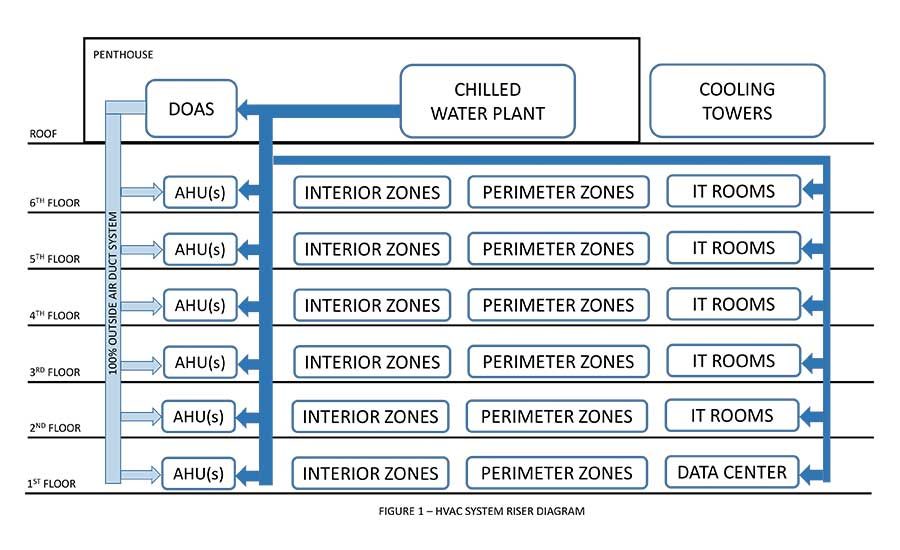
Figure 1 shows a riser diagram of a large (i.e. greater than 300,000 square feet) commercial building that is being designed with an HVAC system comprised of: (1) a dedicated outside air system (DOAS), (2) a water-cooled chilled water plant, and (3) an air-handling unit (AHU) on each floor. Each AHU serves various interior and perimeter zones. The chilled water plant serves the DOAS as well as the AHU’s various IT rooms and small data centers distributed throughout the building. For simplicity, the heating plant, terminal units, and other HVAC system components are not shown in the figure or described in the article.
Due to various humidification requirements or building constraints (i.e lack of outside air intake louver area), the AHUs throughout the building are not being provided with air-side economizers. As such, and per the requirements stated in IECC, a water-side economizer is provided in the chilled water plant. Depending on the climate zone in which the project is located and on the code-compliance path chosen by the project team, the water-side economizer can be done in series (i.e water flows first through the heat exchanger and then to the chillers) or parallel (i.e heat exchanger is in parallel with the chillers). Figure 2 shows a diagram of a chilled water system with a parallel water-side economizer. Chilled water is provided via two water-cooled centrifugal chillers. The design chilled water supply temperature (CHWS) is 40°F and the design chilled water return temperature (CHWR) is 54°. For a building this large and with loads relatively complex, cooling is required throughout the entire year; chilled water will need to flow through the chillers or the heat exchanger.
When designing this type of HVAC system, designers will need to consider if the DOAS should be provided with a cooling coil or not. In either case, energy will need to be spent to condition the outside air that is being delivered throughout the building; this can be done solely at the AHU level or at the DOAS and AHU level. The location of the DOAS is one of many factors that will need to be analyzed before making such a decision. If the DOAS is located farther away from the plant relative to the rest of the AHUs (i.e it is on the critical piping path), it may be more energy efficient not to provide the DOAS with a cooling coil. This approach will eliminate the need for the chilled water pumps to send significant amounts of water toward the end of the chilled water piping system. If the DOAS is located in close proximity to the chilled water plant, as shown in Figure 1, it may be more energy efficient to provide the DOAS with a cooling coil. This approach may result in a decrease of the size of the motor of the chilled water pumps.
A typical configuration of a DOAS with a cooling coil is shown in Figure 3. In many instances, an energy recovery section is included with the DOAS. The energy recovery section can be an enthalpy wheel or a run-around coil. The designed operating conditions in the winter are also shown in Figure 3. The design heating water supply (HWS) temperature is 150°, and the design heating water return (HWR) temperature is 110°. The preheat coil is sized to heat 60,000 cfm of outside air from 9°-40°. Assuming fan heat gain of approximately 4° and a duct temperature gain of approximately 1°, the DOAS supply temperature would be approximately 45°. Because the AHUs serve both interior and perimeter zones, it’s critical the outside air temperature (OAT) being delivered by the DOAS to the AHU(s) is as low as possible in order to minimize the cooling energy at the local AHU. An associated preheat coil (PHC) control’s sequences of operation may be as follows: (1) When enabled, the DOAS controller shall modulate the PHC valve and to maintain the PHC discharge air temperature (DAT) heating set point, which is normally limited to 40° (adj.); and (2) the preheating control valve shall be enabled whenever: (i) the outside air temperature is less than 39° (adj.), (ii) and the supply fan(s) status is on, (iii) and the cooling is not active, (iv) or when the DOAS is stopped and the OAT is less than 40° (adj.). The controller shall maintain PHDAT at 40° (adj.), with a low limit alarm at 35° (adj.). As can be seen from the sequences of operation described above, there is no flow through the chilled water coil when heating is active; however, and assuming that a face and bypass damper have not been provided on the chilled water coil, air will continuously flow across the coils. This means that fan energy will always be spent to pull the air across the heating coil and cooling coil.
Based on the above, can chilled water be used as a heating medium in lieu of hot water? What if we allow chilled water to flow through the chilled water coil and modulate the PHC valve to maintain a PHDAT of 35° (adj.)? Can energy be saved with this approach? If the answer is yes, then what are the risks, and what are the associated risk mitigation strategies? Figure 5 shows a potential design that uses chilled water as a heating medium.
One may recognize that the approach described above will tend to push the comfort limits of many designers, in particular as it relates to freeze protection. Further, in order to implement a strategy such as heating with chilled water, the associated sequences of operation will need to be, at minimum, sophisticated. Commissioning such a strategy will also have its own challenges. Typically, the commissioning authority CxA simulates set points and conditions when commissioning the HVAC system. Because of the sophisticated nature of this approach (i.e heating with chilled water), the CxA will most likely need to test such a strategy after the building is occupied and the HVAC loads in the building have stabilized (i.e one year into occupancy). During this time, the risk of having something go wrong while the building is fully operational is significantly higher.
However, in order to minimize and mitigate such risks, at minimum, the following design strategies will need to be implemented: (1) reset the design chilled water supply and return temperature; (2) install highly accurate temperature averaging sensors and a freezstat; (3) install high-performance water flow meters on each coil; (4) select chilled water coils to allow for both modes of operation (i.e summer cooling and winter heating); (5) utilize BACnet IP controllers for the chilled water plant, hot water plant, AHUs, and DOAS; and (5) design new sequences of operation. The new sequences of operation may be as follows: (1) When enabled, the DOAS controller shall modulate the PHC valve and maintain the PHC DAT heating set point, normally limited to 35° (adj.), and shall modulate the cooling coil control valve to maintain a cooling coil DAT of 45° (adj.); (2) the preheating control valve shall be enabled whenever: (i) The outside air temperature is less than 34° (adj.), (ii) and the supply fan(s) status is on, (iii) and the cooling is not active, (iv) or when the DOAS is stopped and OAT is less than 40° (adj.). The controller shall maintain PHDAT at 40° (adj.) with a low limit alarm at 35° (adj.).
Additional sequences of operation that will need to be considered by the designer are those related to the chilled water temperature reset strategies. This can be done by having the chilled water plant controller monitor the position of the chilled water control valve associated with each AHU and IT room terminal unit in order to ensure the cooling loads are satisfied throughout the entire building.
Lastly, but not less importantly, the designer will need to properly design and select the cooling coils and associated terminal units that serve the IT spaces in order to ensure the referenced cooling coils can satisfy the IT loads based on the two sets of chilled water temperatures (i.e. summer mode and winter mode). It’s worth mentioning the 2016 version of ASHRAE TC9.9, shown in Table 2, shows the IT room design temperature could be as high as 100°. This should provide the designer with greater flexibility when designing terminal units (i.e CRAC units with chilled water coils) that serve IT spaces.
As shown in Figure 6, a new chilled water system bypass valve may be installed. Depending on the IT loads and the building’s interior loads during the winter season, it may be possible for the chilled water system to reach an equilibrium such that one can not only shut down the chillers but also the water-side economizer. In this scenario, an additional bypass valve will be required to be installed on the chilled water coil; this is to divert the water flow coming out of the coil (typically this is chilled water return) into the chilled water supply piping.
HVAC technologies are changing at a breathtaking pace. Typically, the latest and most energy-efficient HVAC equipment comes with a cost premium that cannot be supported by many projects. Oftentimes, when attempting to design an energy-efficient system while staying within the project budget, the burden falls on the designer. As such, HVAC system designers must look at things from many perspectives. Don’t be afraid to push the boundaries of what can be done with proven technologies.


