
It is the opinion of these authors that designing a central utility plant (CUP) presents the most exciting engineering challenge in one’s career. Sizing the HVAC equipment, laying out the piping systems, and designing the controls architecture in a CUP is a formidable challenge, particularly when the project involves large-capacity equipment (in this case, 4,000 tons of cooling). Add to this that the plant is located in a hospital and the project is located in a seismic zone with a seismic design category of C (or D) and the need for a well-engineered solution is at a maximum.
In addition to the applicable minimum code requirements, the layout of the CUP must take into account the available space, flexibility for future expansion, the desired efficiency of the CUP cooling and heating systems, operational needs, redundancy requirements, and resiliency needs.
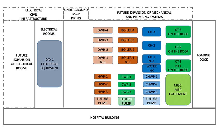
Figure 1 shows the “day one” layout of a sample CUP meant to serve a hospital. In this scenario, the main HVAC and plumbing systems located in the CUP are comprised of the following:
- three water-cooled centrifugal chillers arranged in an N+1 configuration;
- four gas-fired condensing boilers arranged in an N+1 configuration and;
- four gas-fired domestic water heaters also arranged in N+1 configuration.
In addition, all pumps in the CUP are arranged in an N+1 configuration, with the cooling towers serving the chillers located on the roof of the CUP.
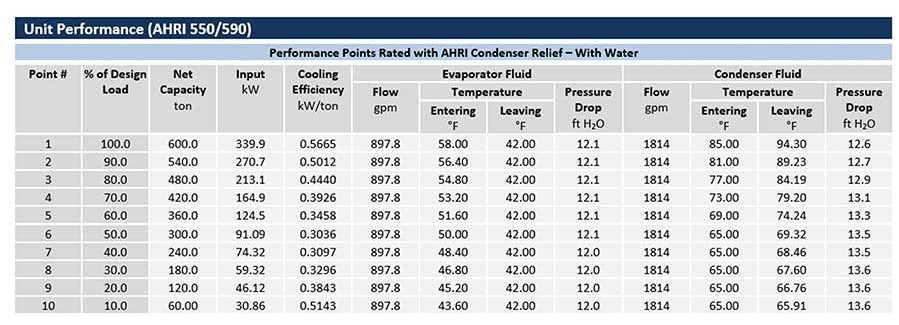
The first step in designing a CUP that is flexible enough to accommodate future expansion is to understand any potential for the physical expansion of the hospital or other buildings located near the hospital, such as medical offices. One way to account for future growth is to oversize the equipment in the plant. This approach has limitations, namely that having grossly oversized chillers operate at low-load (day-one) conditions for long periods of time. This is likely to be less efficient than having chillers that are right-sized to day-one loads operating above 50% loading for most of the time. As shown in Figure 2, the efficiency (in kW/Ton) of a water-cooled chiller starts decreasing once the chiller is loaded below 40%, with the most efficient energy efficiency loading being at approximately 50%.
Design for Future Expansion
Another way to accommodate for the future growth of a hospital or campus is to design the section of the building that houses the CUP for physical expansion. When implementing this design approach, it is important to identify in the day-one design the areas on the site near the CUP where the civil connections will be made. An example of this type of infrastructure is the underground electrical duct banks between the generators and the electrical gear that is located inside of the CUP. Another intangible benefit of having areas of future CUP expansion clearly identified in the contract documents is that it will help the future designers have a better understanding of the original design intent.
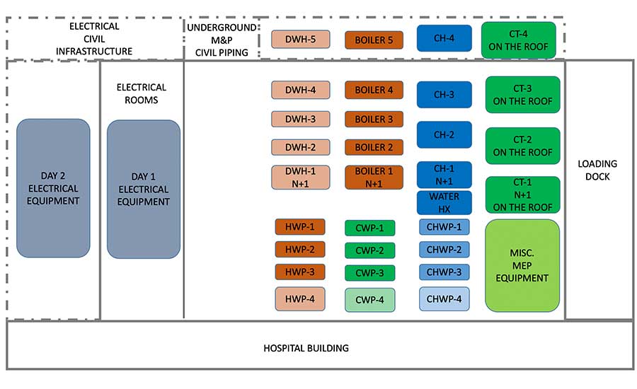
Figure 3 shows a “day two” potential future layout of the CUP where an additional chiller, boiler, and domestic water heater have been installed in the expansion of the CUP while the new condenser water, chilled water, and heating hot water pumps have been installed inside space planned within the original footprint of the CUP.
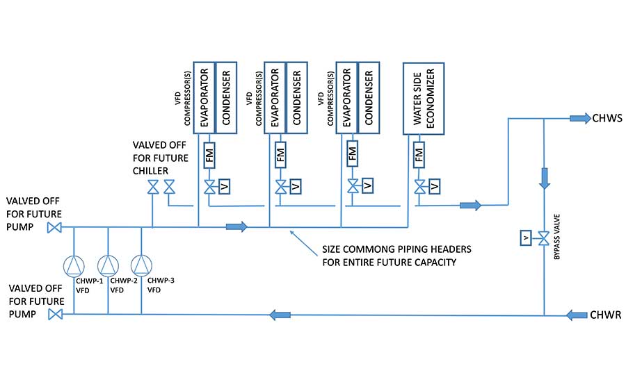
From the perspective of the approach to piping design, it is important to size the piping headers of the CUP for the entire capacity of the CUP. To support this approach, a manual isolation valve can be strategically placed so that new equipment can be added to the CUP without the need to shut down the operation of CUP. Refer to Figure 4.
It is the opinion of this author that highly accurate water flow measuring devices and motorized analog control valves should be provided for each piece of hydronic equipment that are part of the CUP, including boilers, chillers, and cooling towers. Inline electromagnetic water flow meters are an example of a highly accurate water flow measuring devices, as are wet/wet differential pressure transmitters provided with five-valve manifold assemblies. Using this type of highly accurate sensors serves, at minimum, two purposes:
- Building automation system (BAS) can equally distribute the flow of water across multiple operating machines.
- The rebalancing of the existing CUP equipment is minimized when new equipment is added as part of an expansion project.
Independent Operation
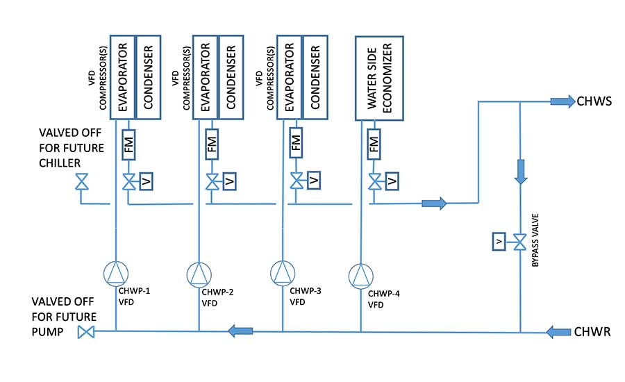
A holistic approach to designing resiliency into the CUP is to ensure all equipment is independent, where operation of one piece of equipment is not dependent on the successful operation of another system or piece of equipment. Figure 5 shows the schematic piping diagram of a variable primary configuration for a CUP chilled water system. A modulating bypass valve is provided to ensure that the minimum required chilled water flow is always maintained thru the operating chillers. However, in this scenario, each chiller is assigned a dedicated primary chilled water pump. In this arrangement, should a pump fail, the BAS must also fail the chiller associated with the pump that failed, even though that chiller has not experienced a failure condition.
Unlike the piping arrangement in Figure 5, the piping arrangement in Figure 4 shows the variable primary chilled water pumps connected into a common piping header. This approach allows the BAS to pair the operation of any chiller with the operation of any pump. Further, this approach allows the BAS to equalize the run time of each chiller independent of the pumps, extending the useful life of all equipment and improving operations during changeover of lead lag equipment. This is because lead-lag changeover of chiller and pump at the same time in dedicated piping arrangement will most likely negatively impact the short term water flow thru the CUP.
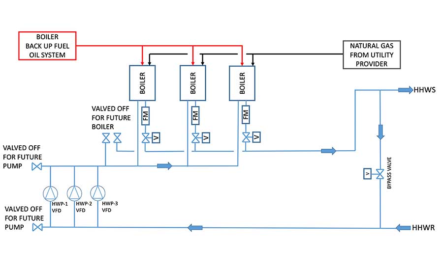
As shown in Figure 6, the same approach could also be implemented for the CUP heating system. However, when designing CUP heating systems that serve hospitals, the code— Facilities Guideline Institute (FGI) and, by reference, ASHRAE 170 Ventilation of Healthcare Facilities — requires that a backup fuel source be provided to support the CUP heating systems. This code requirement is typically met by having on-site fuel oil storage and a distribution system that turns on when there is an interruption of the natural gas (primary fuel source) supply to the building. When selecting boiler manufacturers that are allowed to bid on the project, it is important that the designer of the CUP heating system clearly define the requirement for boiler burners capable of operating in a dual-fuel configuration. Additionally, the construction of the boiler’s heat exchanger must account for the dual-fuel mode of operation to prevent premature failure of the boiler metal alloys due to the more corrosive fumes that are generated when the burner is using fuel oil.
Seismic Events
Designing a CUP that can remain fully operational during and after a seismic event requires a deep understanding of the applicable codes and limitations of professional liability. The code that defines seismic requirements for nonstructural building components is ASCE Standard 7: Minimum Design Loads and Associated Criteria for Buildings and Other Structures, specifically Chapter 13. Per ASCE, any component, inclusive of MEP systems or portions thereof, that are “….attached to an Occupancy Category IV structure and it is needed for continued operation of the facility or its failure could impair the continued operation of the facility” is assigned a component importance factor (Ip) of 1.5. Since, per code, a hospital is a Category IV structure, the referenced ASCE requirements means that any component installed in the CUP must:
- be fabricated to withstand a seismic event and continue to operate after a seismic event;
- be installed so that it can withstand a seismic event.
Chapter 13.2.2 Special Certification Requirements for Designated Seismic Systems of ASCE defines the requirements that manufacturers of components, e.g. boilers, chillers, pumps etc., must follow in order to obtain a seismic certification of their components.
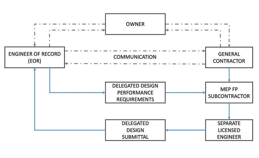
From the perspective of installing the CUP components, the engineer of record (EOR) for the CUP is typically not responsible for the design of hangers, guides, anchors and / or expansion joints that are to be provided for the systems located inside of the CUP. This scope of work is a delegated design item within the project specifications. A sample definition of delegated design could be “a portion or component of the work identified by the contract documents that is to be designed by the contractor, or an entity assigned by the contractor, to satisfy performance and design criteria specified in the contract documents for that portion or component.” Further, the EOR may also ask of the contractor to hire a registered design professional to perform any required calculations associated with the delegated design services.
Design Professional Definition
A sample definition of a design professional could be “an individual who is responsible for providing the delegated design work, and for certifying that the work is in compliance with the specified performance requirements and design criteria. Design professional shall be legally qualified to practice in jurisdiction where project is located and shall be experienced in providing delegated design services of the kind indicated. Delegated design services are defined as those performed for installation of the system, assembly or product that are similar in material, design, and extent to those indicated for this project.”
The above means that the EOR is asking of the contractor to perform design services and that the majority (not all) of the professional liability associated with the delegated design services is on the contractor and not on the EOR. However, the EOR still has a responsibility to establish the performance criteria that the contractor must follow when performing delegated design services, and review the delegated design that the contractor will perform. This is done by asking the contractor to submit a delegated design submittal, which typically includes drawings, calculations, specifications, and other documentation provided, sealed, and signed by registered design professional.
It is important to note that, even though an EOR delegates the design of certain systems (hangers, guides, supports, etc.) to the contractor, the EOR must still endeavor to account for the provision of these piping and ductwork appurtenances when laying out the CUP. Failure to do so may result in a significant amount of constructability issues during the construction administration process. This lack of coordination is typically resolved at the cost of valuable space for operations and maintenance.
Designing a CUP is a complex and crucial task, requiring a deep understanding of the owner’s goals and objectives. Because the CUP serves as the heart of a facility, its reliability, resiliency, ease of maintenance and energy efficiency are crucial in having the facility provide its occupants with the services they need while helping to ensure their comfort and safety.
Designing a CUP can be an exhilarating and fulfilling challenge for engineers who are passionate about their work. While the task may be daunting at first, it presents a unique opportunity to showcase creativity, problem-solving skills, and technical expertise.
In conclusion, the challenge of designing a CUP is an opportunity for professionals to demonstrate their skills, creativity, and passion for engineering. The complexity, technical mastery, continuous learning, impactful contributions, and the collaborative nature of the work make it an exciting endeavor that drives the engineers to embrace the challenge and deliver outstanding results.


