
In general, the energy consumption of commercial HVAC systems represents a significant portion of the overall building energy consumption. Within an HVAC system, typically, the chilled water and heating hot water plants are the largest energy users and have the highest first cost. When it comes to the design of chilled water and heating hot water plants and their associated piping and pumping systems, the industry literature is exhaustive, to say the least.
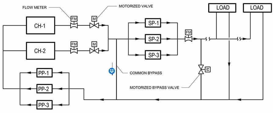
One of the most typical chilled water plant pumping and piping arrangements is the primary-secondary system. As show in Figure 1, the chilled water primary-secondary system consists of two piping loops, which are separated by a common bypass pipe. The primary loop is dedicated to the chillers, and the secondary loop is dedicated to the loads in the building. One of the main reasons behind using this pumping approach is the sensitivity of the chillers to variations in the water flow through the chiller evaporator bundles. To mitigate the risk of having the chillers tripping due to insufficient flow through the evaporator, the pumps in the primary loop (i.e., PP-1 and PP-2) are sized for the design flow of the chillers and are operated at constant speed. The operation of each pump can be integrated with the operation of each chiller, or it can be staged such that any pump can be integrated with any chiller based on run time and/or fault conditions; however, and in order to prevent backflow through a chiller that is not operating, a motorized isolation valve will need to be provided for each chiller. The speed and staging of the secondary pumps (i.e., SP-1, SP-2, and SP-3) is modulated by a building automation system (BAS) to maintain a differential pressure set point in the piping system. Typically, at least one differential pressure sensor is installed at the extreme end of the piping system.
The purpose of the common bypass pipe located upstream of the secondary pump is to ensure sufficient water flow is readily available to the chillers during low-load conditions. Since the common pipe is a critical design feature in the operational safety of the chillers, appropriate sizing of the bypass is required. For instance, an oversized pipe allows the intermixing of fluids and affects chiller optimization due to varying inlet temperature, whereas an undersized bypass might fail to provide the necessary minimum flows to the chiller.
Controlling the up-staging of the chillers and the associated primary and secondary pumps needs to be done in at least three stages. In the first stage, the BAS will need to check for any faults at the standby chiller(s), pumps, and valve actuators. Once the BAS has detected there are no faults with the standby plant equipment, the BAS will then enter the second stage, open the motorized isolation valves, and turn on the standby pumps. Upon sensing proof of the required flow through each chiller, the BAS will enter the third stage and enable the standby chiller(s) to run and maintain the associated chilled water temperature set points. It is important to note that ASHRAE Guideline 36 describes in more detail various sequence of operations (SOOs) that could also be used when designing controls systems for chilled water plants. The SOOs described in this article are SOOs the authors have succefully designed and implemented on chilled water plants with a capacity ranging from 1,000-2,400 tons.
SOOs for establishing an overall design intent for the BAS programmers could be: a) The chillers are staged based on secondary chilled water system flow rate; b) When the system is enabled, the first-stage chiller shall operate; c) When the secondary system flow rate exceeds 1,500 gpm (adj) for more than 15 minutes (adj), a stage-up event shall occur, and the second-stage chiller shall be initiated as described below; d) If the second-stage chiller is operating, and the secondary chilled water system flow rate falls below 1,800 gpm (adj) for more than 15 minutes (adj), a stage-down event shall occur; e) The system shall prohibit a new stage-up or -down transition for 20 minutes (adj) after a stage-up or stage-down transition. This allows steady state to be achieved and ensures a minimum on and off time before changing stages; and f) The secondary chilled water pump staging and speed control logic shall be independent of the primary system staging sequence.

SOOs for the first stage — The BAS checks for faults, assuming that at least one pump is operating and chiller control valves are open : a) The BAS shall check for minimum flowrates through the first-stage chiller condenser and evaporator, as seen by the associated flow meter, and the first-stage chiller control panel will check for minimum flowrates through the interlocked factory-provided, field-installed flow switches; the chiller shall not start unless both the flow meters and flow switches show that minimum flow is achieved; b) If no flow is registered on the evaporator side 30 seconds (adjustable) after chilled water pump status is proven, the associated chiller’s chilled water isolation valve will be failed. Failure of an isolation valve will fail the entire chiller; c) If no flow is registered on the condenser side 30 seconds (adjustable) after the condenser water pump status is proven, the associated chiller’s condenser water isolation valve will be failed, and failure of an isolation valve will fail the entire chiller; d) If no flow is registered at the cooling tower 30 seconds (adjustable) after the condenser water pump status is proven, the associated cooling tower will be failed; and e) If failure is seen in any equipment or minimum flow is not achieved, generate an alarm and move on to next associated unit in the respective sequence.
SOOs for the second stage — The BAS slowly turns on pumps and opens isolation valves: a) Lock the first-stage primary chilled water pump and condenser water pump speed at their current setting, and command the operating chillers to reduce demand to 50% of their current load. Wait until the actual demand is less than 55% up to a maximum of five minutes before proceeding; b) Start the next condenser water pump and slowly open the condenser water isolation valve of the chiller that is to be started. The purpose of opening up the valve slowly is to prevent sudden disruption to flow through the active chiller. The valve timing and pump ramp-up timing must be determined in the field as required to prevent nuisance trips and minimum fluctuation of flow through the first stage chiller; c) Start the next primary chilled water pump and slowly open the chilled water isolation valve of the chiller that is to be started; and d) Ramp up the second-stage chilled water and condenser water pumps until their speeds are equal to their associated first-stage pumps.

SOOs for the third stage – The BAS enables the standby chillers to run: a) Start the next-stage chiller after the associated chilled water isolation valve is fully open or after a minimum time delay as recommended by the chiller manufacturer, whichever is more. The final time delay will be determined in the field as required to prevent nuisance trips; b) Release the primary chilled water and condenser water pump speeds and modulate the first- and second-stage pumps in unison to maintain the system flow rate set point; and c) Release the first-stage chiller demand limit.
It's important to note the speed of the secondary chilled water pumps is independent of the operation of the primary chilled water pumps. However, the control of the secondary chilled water pumps is just as important as the staging and control of the primary chilled water pumps. Figure 2 shows sample pump selection information that is typically provided as an output from a pump selection software. In addition to the design criteria for the pump, the software also states the minimum flow required through the pump. A design engineer will need to ensure the minimum speed setting of the pump is selected such that the pump does not operate close to or below the minimum required flow through it, because operating the pump in low-flow conditions could cause overheating and decrease the life expectancy of the pump’s bearings.
To better control the minimum flow through the secondary chilled water pumps, a bypass valve will need to be provided just downstream of the pumps. A flow meter should be installed on the main chilled water supply line, downstream of the chilled water secondary pumps, and upstream of any loads. Similar to the staging of the chillers and associated primary chilled water pumps, the BAS will use a staging approach, as follows:
SOOs for establishing an overall design intent for the BAS programmers: a) The secondary chilled water pumps shall be started and stopped according to the chiller loading and chiller unloading sequences when a chiller is enabled or disabled; b) The BAS shall assign to each secondary chilled water pump a corresponding stage number based on run time; and c) The secondary chilled water pumps are configured in a manner that if the operating duty pump should fail, as sensed by a mismatch between the BAS's controlled valve and the BAS status monitored by associated current transducers, the BAS would start the standby pump and disable the failed pump from the BAS controlled operation.

SOOs for the first stage – the BAS checks for faults, assuming that at least one pump is operating and chiller control valves are open: a) The BAS shall monitor the alarms at the associated pump motor variable frequency drive (VFD), and if a secondary chilled water pump should fail, an alarm shall be generated; b) The BAS shall automatically start the next pump to replace the failed pump, and the enabled chillers shall remain enabled and the "failed" secondary chilled water pump shall be disabled; c) Should no other secondary chilled water pump be available, the BAS will stage off the associated chiller, cooling tower, and condenser water pump; d) Secondary chilled water pumps that fail during operation shall automatically be assigned a designation of "failed/maintenance," and secondary chilled water pump failure shall include loss of status, a VFD fault, and designation (by the building engineer) of "failed/maintenance;" and e) Failed pumps must be manually reset by the operator at the operator’s work station (OWS).
SOOs for the second stage — BAS enables the secondary chilled water pumps: a) The differential pressure set point shall be optimized using feedback from system valves, and the BAS shall vary the speed of the secondary chilled water pumps to maintain differential pressure set point(s) as sensed by the differential pressure (DP) sensors connected between the supply and return chilled water piping; b) The BAS shall automatically alternate the operation of the duty and standby secondary chilled water pumps on a lead-lag arrangement based on a run-time schedule; and c) The remote DP set points will be maintained between maximum and minimum pressures. The maximum differential pressure limit is the pressure required to provide full flow to all control valves simultaneously, and the minimum differential pressure limit is the pressure correlating to the lowest speed the pump is allowed to be operate at based on minimum chilled water flow and minimum pump flow while maintaining the minimum pressure required for piping system accessories to function properly.
SOOs for the third stage — BAS modulates the bypass valve: a) When chilled water pump(s) are operating at minimum speed and the chilled water differential pressure in the system is greater than its maximum limit, the bypass valve will modulate open to relieve pressure in the chilled water system; and b) The bypass valve shall modulate open to maintain a minimum system flow rate as determined during startup/ tuning. The minimum flow rate shall correspond to the pump flow at its minimum operating point.
An alternative to the primary-secondary pumping and piping arrangement is the variable-primary system. As shown in Figure 3, this piping arrangement consists of only one set of pumps; the secondary pumps have been removed and the flow through the evaporator is allowed to vary. The speed of the primary pumps is now controlled to maintain the DP set points in the piping system and to maintain the minimum chilled water flow through the chillers or the minimum flow through each operating pump, whichever is higher.
In the case of the condenser water system, it is almost an industry standard to not vary the condenser water flow through the chiller condenser bundle. This is because varying both the chilled water flow and condenser water flow through a chiller will require complex, and most likely difficult to implement, SOO in order to prevent the chiller from tripping due to low or high head pressure. However, this does not mean pump energy cannot be saved. As the outside air wet bulb temperature decreases, the tower will need less airflow to maintain the condenser water leaving temperature set point, and the BAS will start ramping down the tower fan speed; when the tower fan is operating at its minimum allowable speed set point, the BAS will open the tower bypass valve and bypass condenser water into the tower basin, as shown in Figure 4. Flow meters and motorized control valves should be designed for each tower to ensure the condenser water flow is evenly distributed across the operating towers.
A few potential pitfalls while designing condenser water systems and selecting condenser water pumps, if not avoided, could lead to catastrophic failure or damage to the system and its components. Some of these pitfalls are incorrect pump head estimation and air in pump suction, leading to cavitation.
It’s important to determine the correct pump head considering whether the tower is a closed or open loop. In a closed-loop circuit, the static head determination might not play a significant role, as the static head required to pump water to the top of the elevation is cancelled by static head regained as water flows down the return piping. Whereas, in an open-loop circuit, it’s critical to determine the tower static head because of the open height of the piping circuit. The pump head estimation calculations need to take into consideration the static head necessary to raise water from bottom to top of the cooling tower as well as incorporate any of the friction losses through piping, chiller condenser bundle, cooling tower, and valves.
Further, air into the suction line of the pump could also be drawn due to insufficient water in the tower basin, which, upon pump startup, would lead to the draining of the basin or lower its water level, leading to the formation of vortices.
Cavitation is an extremely important factor that could contribute to severe damage of condenser water pumps. Cavitation occurs when the pressure at the inlet of the pump is less than the net positive suction head (NPSH). Pump cavitation could be prevent by implementing some of the following: a) Electronic level sensors; b) Design of bypass; c) Proving flow in enabled tower prior to enabling next pump; d) Limiting suction piping positive displacement (PD); e) Placing cold water (CW) strainers on discharge side of pumps; f) Ensuring construction strainers are removed from pump suction diffusers; and e) Providing motorized isolation control valves on both sides (supply and return) of each cooling tower.
No matter how well pumps are being selected and piping is sized, if the associated controls sequences are not properly designed and implemented, then the potential of having an energy-efficient chilled water plant is significantly reduced. Lastly, having the proper BAS sensors and actuators is just as critical; one cannot properly control what one doesn’t measure.


