
This article describes the remodeling of a hospital kitchen in which workers experienced high temperature and humidity levels as well as turbulent airflows most of the year. Causes included both over and under specification of kitchen appliances and HVAC equipment. Among other issues, the kitchen was built, surprisingly, without mechanical cooling. At great expense, the kitchen was remodeled with an integrated solution that’s providing significant improvements in the kitchen environment.
Symptoms
-
High makeup-air temperatures affected the entire kitchen all year-long, adding to the usual high temperatures on the front appliance line, especially during intensive cooking times. The highest kitchen temperatures occurred on an especially hot summer day when the outdoor temperature was 90°F, but the incoming air to the kitchen makeup unit was measured as 111° from solar heating of the roof area.
-
High humidity levels were routinely experienced in the kitchen during intensive cooking times and especially during and after dishwashing operations.
-
There were also turbulent air currents in the kitchen, which were related to the supply and exhaust air amounts, diffuser types and locations, and probable fan performance issues.
Examination
The hospital kitchen generally operates from 6 a.m. through 7:30 p.m. daily, serving about 1,100 meals per day to patients, staff, visitors, and patrons of on-site medical offices. Additional “short order” cooking operations are conducted in an adjoining café, which was not involved in the remodeling described below.
Task Group
After the record uncomfortable day described above, the hospital staff architect convened an expert task group to examine the kitchen discomfort issues. Participants included a contract kitchen manager, contracted senior mechanical engineer and engineering consultant with expertise in commercial kitchen ventilation, a food service design consultant, and a sales engineer from a prominent kitchen ventilation manufacturer.
The task group purposefully included experts new to this project to provide a fresh look at the troublesome design issues. The group began their work by establishing a baseline of the kitchen and rooftop equipment most likely contributing to the significant comfort issues.
Regarding the cooking appliances and main exhaust hood, the appliances were diverse, including range tops, a charbroiler, a steamer, a tilting skillet, and deep fat fryers along with two sets of double stacked convection ovens — all fueled with natural gas. From a mechanical code viewpoint, the appliances were medium and heavy-duty, with many of the appliances generating significant convective and radiant heat loads to the cooking area. The appliances were arranged into main and secondary cooking lines, back-to-back, over which four Type I (smoke and grease) wall canopy hoods were arranged two-by-two to form one large rectangular island hood.
The bain-marie hot water bath appliance was positioned near one end of secondary cooking line and exhausted by a simple Type II (heat and water vapor) hood with its own small exhaust fan.
To address the initial discomfort issues after the kitchen began operating years earlier, a portable, 20-ton rooftop unit had been installed with temporary ducting to diffusers in the kitchen. One very large rooftop exhaust fan was intended to remove cooking effluents from the four sub-hoods comprising the large island hood.
A makeup-air unit had been installed during original kitchen construction with heating but no cooling capability. Makeup air was being discharged through somewhat randomly placed high-velocity diffusers in the kitchen. Hospital engineering staff indicated that a mechanical contractor had been retained periodically to rearrange kitchen air supply and return diffusers in an unfulfilled effort to improve kitchen comfort.
Two large propeller cooling fans on tall pedestals were located near both ends of the front cooking aisle, blowing air toward the front cooking line in an effort to aid worker comfort; however, it was apparent that these fans were more detrimental to hood capture and containment performance than helpful for comfort.
During new construction, a very large (16-foot-long) flight-type conveyor dishwasher was installed in a three-sided partitioned area of the kitchen. The ends of the machine were partially closed by plastic strip curtains with a central exhaust outlet ducted to a rooftop exhaust fan.
Diagnosis
After a full examination of all equipment and operational factors causing kitchen discomfort, the task group summarized the causes of comfort issues:
-
The main hood exhaust rate and canopy overhangs on all open hood sides were insufficient to capture and contain heat, water vapor, and grease effluents as confirmed by the use of a small, disposable smoke puffer.
-
The exhaust hood design was quite unusual with a half-cylindrical inner, upper surface. It was designed to direct effluent up the backs of the hoods and then down the fronts of each hood, inside of which grease filters were installed. In spite of the intended performance, testing with the smoke puffer showed that effluents mostly spilled downward and outward from the hood fronts because the effluents did not make the intended 90-degree turn into the filters.
-
Air turbulence near the main hood was measured by a small swing vane anemometer. Under the front left corner of the main cooking line hood, air was blowing toward the hood from two high-velocity ceiling diffusers over 10 feet away with airspeed varying from 0-150 FPM. This airflow oscillation suggested that one or more supply or exhaust fan was operating in the “range of instability” due to high static pressure.
-
Instead of enhancing comfort, the two large pedestal fans pointed toward the front cooking line added to effluent spillage from the large island hood, including water and grease vapor and convective heat.
-
The use of one single exhaust fan for the large island hood complex was highly energy inefficient as it was operating at full speed during the entire work day, regardless of the highly variable cooking operations on the front and back cooking lines.
-
Visual observation of dishwasher operation showed that much heat and water vapor escaped from the ends of the dishwasher as dishware on the conveyor pushed open the strip curtains, as shown in Figure 1. Analysis of dishwasher specifications indicated that the combined electric and hot water inputs would require 11 tons of cooling to nullify these heat and moisture loads if not fully contained and removed by the dishwasher exhaust fan.
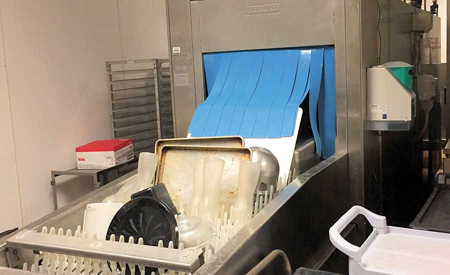
FIGURE 1. A dishwasher strip curtain being pushed open during operation.
-
The bain-marie hot water bath appliance added additional heat and humidity to the kitchen because some of the rising heat and humidity was not fully captured by the Type II exhaust fan.
-
With 87° dry bulb and 73° wet bulb summer design temperatures, the portable 20-ton unit was insufficient for offsetting the combined outdoor and indoor heat and moisture loads in the kitchen.
Treatment
Based on the diagnosis, the task group recommended several equipment and operational changes that were completed by the hospital staff, contract mechanical engineering team, and selected kitchen ventilation supplier:
-
Remove the four hoods comprising the large center island hood and replace with four new, high-quality, listed, aerodynamic hoods that would be made large enough to provide at least 12 inches of overhang on all open sides of the new island hood assembly. To help compensate for the utility pipes and wires between the backs of the appliances, the new hoods were specified to be 66 inches deep to provide more front overhang.
-
Within the hood assembly, include high-efficiency grease filters that are installed in the customary locations in the upper, inside backs of the four sub-hoods. Additionally, specify a hood that has a V-shaped baffle inside the hood front to direct convective heat, water vapor, and grease effluents missing the filters on the first pass of the filters back toward the filters.
-
On the front cooking line, keep the double-stacked ovens positioned on the ends of the cooking line, as they act as hood-end panels to improve hood capture performance.
-
Install a stainless steel baffle between the backs of the front and back appliance lines, starting above the utility pipes and wires, running the total length of the combined hood assembly. This partition helps the four-hood island arrangement to function as two wall canopy hoods back to back to further improve hood performance (Figure 2).
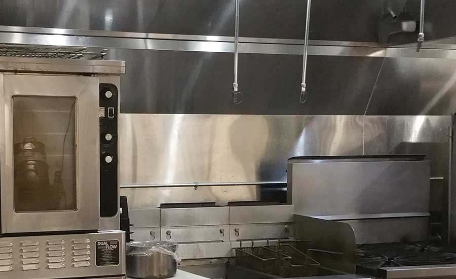
FIGURE 2. A stainless steel baffle between the front and back cooking lines.
-
Replace the single large exhaust fan serving the four sub-hoods and replace it with two smaller heavy duty fans — one for the two front line hoods and the other for the two back line hoods (Figure 3).
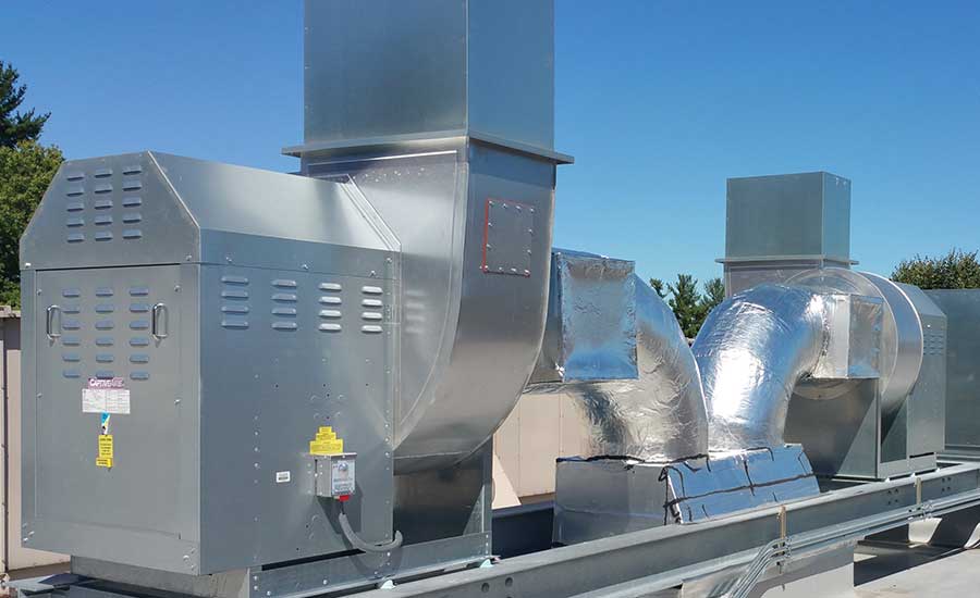
FIGURE 3. New separate exhaust fans for the front and back cooking lines.
-
Remove the portable 20-ton rooftop unit and temporary ducting and replace it with a 20-ton variable volume unit with new air ducts to kitchen diffusers.
-
Remove the small heat-only makeup unit and install a new dedicated modular makeup air system with direct-fired, variable gas heating and 30 tons of two-stage cooling with a variable speed supply fan (Figure 4).
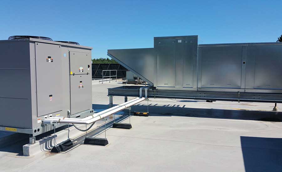
FIGURE 4. A two-stage, 30-ton condenser (left) and modular makeup unit (right).
-
Install integrated demand controls for the new exhaust and makeup fans with VFDs, soft starts, and a low-speed morning “prep” mode. Electronically control the front and back line exhaust fans separately by sensing the respective differences between the average front and back line hood internal temperatures and the mean kitchen temperature.
-
Install combined perimeter perforated makeup and recirculating air plenums with low-velocity, downward air distribution mounted outside all open sides of the large island hood assembly and the separate bain-marie hood. Feed partially tempered makeup air to the inner perforated plenum sections and feed fully tempered recirculating air to the outer perforated plenum sections.
-
Replace the original high-velocity ceiling air diffusers with lower velocity diffusers away from the cooking lines and use a building information system’s 3-D images of the area above the lay-in kitchen ceiling to ease the placement of rooftop equipment, ducts, and diffusers (Figure 5).
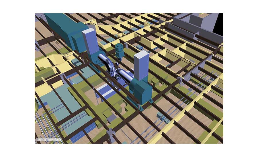
FIGURE 5. A building information system 3D view of construction components and mechanical equipment related to kitchen.
Rehabilitation
Proper commissioning of the new integrated equipment was the final step in improving the kitchen environment and setting up a means of monitoring performance. Setting of exhaust fan speeds was made easier by including their operating parameters in the hospital’s new building management system.
Reduced heating and cooling energy and cost are expected from mechanical code changes and several remodeling actions. A change to the International Mechanical Code section 403.3, beginning with the 2009 edition, requires half of the previously required outdoor air per kitchen worker — 7.5 instead of 15 cfm per person. The added IMC requirement for “area air” is easily satisfied by the amount of outdoor makeup air. These changes enable the use of more partially tempered, dedicated makeup air than before. Additionally, the larger island hood assembly, with greater overhangs and the separating baffle, provide greater hood capture and containment performance, which requires less exhaust air and in turn, less makeup air.
Changing from one to two independent main exhaust hoods with demand controls will also save energy and cost. The exhaust fans are set to provide full capture and containment of cooking effluents at the busiest cooking times, and the demand control system proportionately reduces each cooking line’s exhaust rate up to 20% as respective in-hood temperatures decrease with less front and back line cooking. From fan laws, up to 20% savings in supply and exhaust airflows and related fan speeds should result in up to 50% fan energy savings as well as less heating or cooling of makeup air.
When needed, the new makeup unit heats incoming makeup air delivered to the inner perforated perimeter plenum at 55°. Makeup cooling is set to turn on the first and second stages of cooling (15 tons each) when the incoming outdoor makeup air temperature is greater than 85° and 95°, respectively. Fully tempered recirculating air is furnished to the outer perforated perimeter plenum. Spillage of makeup air into areas outward of the perimeter plenums is minimized by setting downward airflows to the manufacturer’s recommendations for each configuration.
After the remodel was completed, periodic surveys of kitchen temperatures, using handheld infrared thermometers, show conformance with recommended comfort conditions in ASHRAE Standard 55.
Other lessons learned
The initial kitchen specifications were an unfortunate case of simultaneous over and under specification of kitchen appliances and HVAC equipment that led to worker discomfort since the hospital’s construction years ago.
Though food service design consultants often specify exhaust hoods and sometimes other kitchen ventilation elements, the task group assigned this task to the contracted mechanical engineering team because the new hoods, ducts, exhaust fans, and related demand control system; dedicated makeup unit; and perimeter makeup-air distribution system would be completely integrated. One task group member suggested this design consolidation would appropriately “keep the ‘V’ in HVAC,” and the authors highly recommend adopting this design practice.
The conveyor dishwasher was significantly larger than needed in terms of physical size and capacity. The manufacturer’s published capacity for this model is 14,316 dishes per hour. With the kitchen operating 13.5 hours per day, the theoretical capacity would be 193,266 dishes per day for a kitchen that prepares 1,100 meals per day, many of which are provided on disposable serving ware. Though replacement costs dictated keeping the installed dishwashing machine, ventilation in the partitioned area around the machine was improved by adding more supply and return air diffusers in the dishwashing area.


