
In response to consumer demand for higher efficiency boilers and updated regulations from the U.S. Department of Energy, the conversion from noncondensing to condensing vent systems becomes necessary. The benefits of higher efficiency are clear, but this transition comes with its own set of challenges.
Venting 101
To understand the best solution for converting to a condensing vent system, it is important to start with the basics of venting. Most are familiar with the combustion triangle. Combustion requires fuel, oxygen, and heat (ignition source) in proper proportion to occur. The purpose of gas/oil-fired appliance venting is to safely remove products of combustion (POC) from the appliance to the outside atmosphere. Some POC include carbon dioxide, heat, water vapor, and acids/oxides.
For noncondensing boilers and furnaces, the heating temperatures are kept high enough to prevent water vapor in the flue gas from condensing. This is important, because if it does condense, the condensate causes corrosion due to its acidity. And keeping heating temperatures high means less efficiency. By converting to condensing systems, the efficiency of boilers can be significantly increased.
The importance of draft
In the world of vent systems, it’s essential to understand draft — the pressure differential versus atmospheric pressure that drives the flow of gas in a vent. Natural draft is the upward suction caused by the buoyant movement of warm gas within a vertical column. As hot gas rises at the base of a vertical column due to being less dense, it can create a continuous vacuum with a sufficient supply of replacement warm gas. Factors like temperature differential, height, and diameter of the vertical column play a significant role in this process.
When it comes to mechanical draft, there are different types to consider:
- Forced Draft: Creates positive pressure at the beginning and requires a liquid/airtight setup.
- Induced Draft: Operates on negative pressure.
- Combination with inline systems: Utilizes negative pressure up to the inlet and positive pressure after.
Actual Draft is the pressure differential existing in the chimney, which is equal to the sum of natural draft and mechanical draft, minus pressure losses due to flue resistance. By comprehending these draft mechanisms, we can ensure optimal performance.
Category review
Venting systems are divided into 4 categories based on whether there is positive or negative pressure in the vent and whether condensation is continuous.
To read what category a system falls into, draw a large rectangle on a sheet of paper.
Draw a horizontal line through the center.
- Above the line = noncondensing (or not continuously condensing)
- Below the line = continuously condensing vent system
Next, draw a vertical line through the center.
- Left of the line = negative pressure chimney system
- Right of the line = positive pressure
Thus, in the drawing, the upper left corner represents the category I natural draft, the lower left is category II condensing corrosion-resistant. The upper right corner represents category III airtight and the lower right is category IV condensing airtight. In transitioning to condensing vent systems, a common scenario is that we are converting older systems in categories I or III into the condensing categories II or IV.
Why materials matter
When it comes to a venting solution, the selection of materials is crucial to ensure the longevity and efficiency of the system. Materials can vary in durability, from low temperature plastics (LTP) to the most durable stainless steels. Stainless steel such as 29-4C and 316L are used in applications for condensing vent systems due to their ability to withstand exposure to acidic and wet environments. This is especially important as the products of combustion contain a significant amount of water vapor and different types of acids, resulting in a highly acidic condensate with a pH of 3-5, with 7 being neutral. Failure to use the appropriate materials can lead to a short-lived and inefficient venting system. Hence, it is essential to choose resilient materials like specific types of stainless steel to ensure the durability and functionality of the venting system.
Why product construction matters
The type of products used for venting solutions are referred to as special gas vent in the U.S., or BH-vent in Canada. We also refer to them by the Underwriters Laboratories certifications of UL1738, or ULC-S636 in Canada. In addition to proper materials, proper construction of vent lines is critical to a successful venting solution.
Special gas vent lines are manufactured with a male-to-female connection with a gasket which provides a pressure seal. It is important to maintain a slope of ¼ inch per foot for horizontal sections to allow condensate to flow back to a low point, whether in the appliance or inline drain, to be removed from the system and sent to a neutralization kit before discharging into a drain. Additionally, the male-to-female connection allows condensate to flow over the joint rather than directly over the gasket. The gasket is protected in the overlap of each joint, preventing direct contact of condensate. By following these construction guidelines, the life of the gasket is prolonged, and the risk of system failure is reduced, ensuring a safe and reliable gas venting system.
Challenges and solutions
Upgrading ventilation is crucial for high-efficiency appliance venting and though it may be tempting to reuse existing vents, it is not recommended. Existing vents are most likely not made of adequate materials or construction to handle the POC which would lead to corrosions as they rust or deteriorate. Relining an existing chimney with a single-wall vent or flexible stainless product can bring it up to standard and allow for high-efficiency appliance venting.
In cases where a new stack is needed, it’s important to consider the height and size of the stack. We often replace a couple large, individually vented, lower efficiency boilers with multiple smaller, higher efficiency appliances to achieve the same heat load requirements. So, the size of the stack would have to accommodate more appliances being common vented.
Additionally, seasonal load or appliance turndown and the potential of a redundant appliance needs to be considered for the stack. In sizing a vent system, you size for the worst-case scenario, that is full fire for every appliance on the same stack. The challenge is now how to control lower input levels for a high fire sized stack.
Draft control
When designing a system that can function efficiently from low to high fire, an ideal solution is natural draft, which utilizes the buoyancy force of hot air to create a flow in the system. If it is possible in the venting layout, this method is most cost-effective since it doesn’t require any additional equipment and the heat is already there.
Mechanical draft, which involves the use of external fans to create a flow of POC through the system, can be useful in situations where natural draft is not sufficient, or when a more precise control over the system is required.
A fixed blade damper, also known as the “set it and forget it” of dampers, allows for easy control of the system. By adjusting the blade, the draft level can be tuned and locked down for consistent performance at one setting.
An on/off damper uses an actuator to open and close the damper blade. When there’s a call for heat from an appliance, a signal goes to the damper and it opens. When no more heat is needed, it closes. A major benefit of this system is that it is a closed loop. Moreover, on/off dampers prevent movement within the entire vent system. Without one, natural draft could start occurring in an appliance vent that is not in operation (for example, because of a temperature difference between the condition space of the building and the exterior). It will start pulling air through the system. A non-operating appliance bringing in cold air could cause freezing issues and other problems. Additionally, in a positive pressure system an exhaust vent section can be closed off preventing backflow into an idle appliance.
A modulating damper provides the most control to handle all different types of load conditions. It is a combination of a fixed and an on/off damper. The difference is a modulating damper reads pressure in the vent system and the blade will move to hit a specific set point. The damper blade moves up or down to automatically adjust to a specific pressure that the user sets to accurately provide just what is needed for each individual appliance or a common vent.
Overall, the specific needs and requirements will ultimately determine the best approach to a venting solution. With careful consideration of materials and construction, and natural and mechanical draft options (including dampers), it is possible to design a system that can effectively and efficiently address many venting conditions. In short, material matters, draft is your friend, and dampers differ.
Examples
Example 1. Individually vented re-line
At this public building (a courthouse), it was important to check the vent system size on the appliance. In this case, natural draft was able to be utilized without additional devices. As a result, the existing brick chimney was able to be relined with stainless steel. This was a simple solution using the push from the appliance and natural draft that also protected the integrity of the brick chimney with a reline.
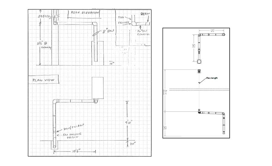
Example 2. Sidewall venting
When upgrading a multi-dwelling building, the building didn’t offer a lot of height for natural draft and reusing the existing vent by relining would be difficult due to several directional changes. The length of horizontal venting on two separate floors exceeded the manufacturer’s allowable equivalent length. The amount of vent before the appliance could not push the POC through. To solve this, mechanical draft was created with inline fans to assist the boiler in pushing POC through and to overcome the pressure losses caused by the changes in direction and horizontal runs. This allowed the exhaust vent to be placed out the side wall, rather than up a tall chimney.
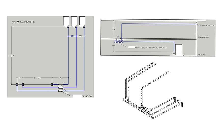
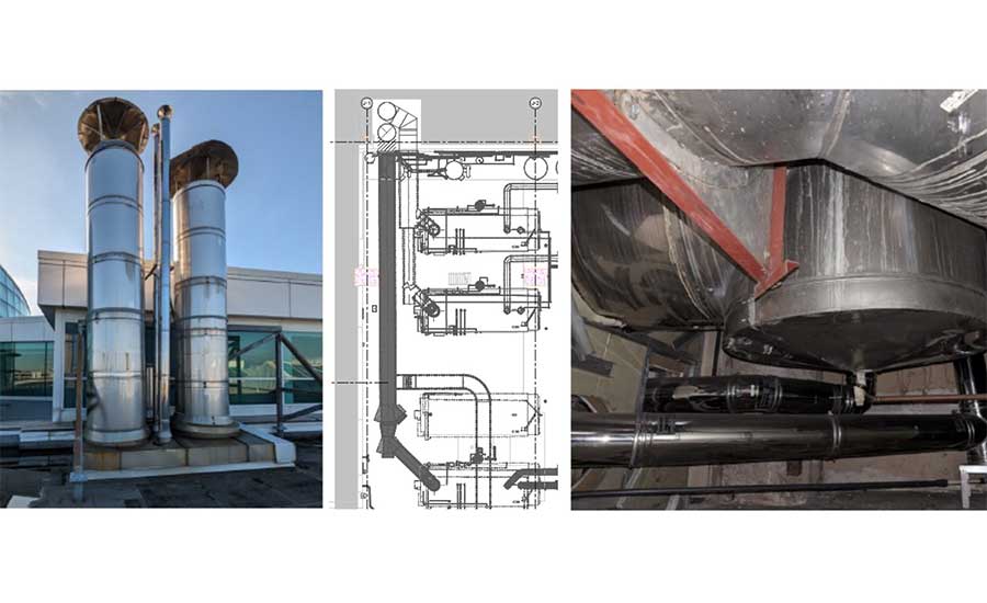
Example 3. Common venting
A more complex conversion at an airport presented many factors to consider and a common vented system. The solution involved relining existing category III chimneys. Several sets of modulating dampers (one for each appliance, one per each fan inlet) were also utilized. This solution included the addition of many different types of devices on a system where the fans communicate with the dampers to adjust for the optimal setting.
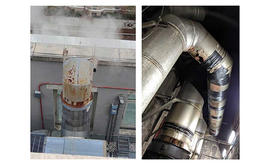
Misguided attempts to reuse existing venting for new appliances are often quick to fail and easy to identify. See Figure 2 (left). A custom-manufactured vent had a cap of unknown material applied and has corroded in just one heating season (right). Existing material was reused on a conversion from a Category I to Category IV. Evidence of condensation eating away at the vent is obvious.


