
Demand Controlled Ventilation (DCV) is a control strategy which aims to vary the amount of ventilation air a system provides a space based on the real-time ventilation requirements (i.e. the ventilation demand) of the space. The term is used in a variety of contexts. Examples include garage ventilation systems which enable and modulate airflow off of measured CO concentrations in the garage, as well as kitchen ventilation systems which enable fans and modulate airflow off of temperature in the kitchen’s exhaust hoods. The example examined in this article is an air handling unit (AHU) whose minimum ventilation requirements are adjusted to meet the varying occupant density of the space it serves. This particular application of DCV has a common misunderstanding which this article seeks to set the record straight on.
DCV in AHUs
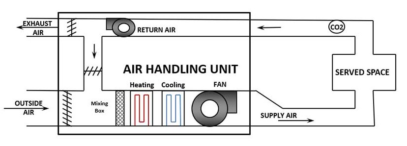
Figure 1 shows an AHU with full economizing capability (i.e. if the ambient conditions are appropriate, it can bring in up to 100% outdoor air). For simplicity, imagine this system serves an assembly area with widely varying occupant density and has constant speed supply and return fans. The total system airflow is 10,000 CFM and the minimum ventilation requirement at design occupancy (referred to as "design minimum" going forward) is 4,000 CFM.
Figure 2 shows the quantity of outdoor air brought into the system as a function of outdoor air temperature. For simplicity, this plot was developed based on the following assumptions:
- Constant speed supply and return fans
- Fixed supply air temperature (SAT) set point of 55°F
- No fan heat gain
- Constant return air temperature of 75°F
- A very dry climate (i.e. an economizer high limit of 75°F ambient temperature)
- No DCV is being implemented

When it is cold out in Stage 1, meeting the design minimum ventilation requirements for the served space will result in the mixed air temperature falling below 55°F, which means the AHU will have to run heat to get the SAT to set point. In Stage 2, the economizer control sequence will bring in higher quantities of outdoor air beyond that of the design minimum ventilation requirements in order to land the SAT at set point without the use of any mechanical cooling. In Stage 3, it is still more energy efficient to bring in higher quantities of outdoor air as it is cooler than the return air, but since the outdoor air temperature is above SAT set point, some mechanical cooling is needed. And in Stage 4, the economizer is disabled as it is no longer advantageous to bring in higher quantities of outdoor air, but the unit must still meet the design minimum ventilation requirements.
It is in Stages 1 and 4 where higher quantities of outdoor airflow result in increased thermal energy consumption. A lot of energy could be saved if the minimum ventilation requirements were reduced during periods when the space was less than fully occupied. A common strategy to estimate occupancy of a space would be to have a CO2 sensor located in the return duct. A drop in CO2 concentration could be used to predict a reduction in occupant density, which corresponds to a reduction in ventilation requirements. Thus, a control strategy measures CO2 and resets the minimum outdoor airflow set point between an upper limit (4,000 CFM in this case) and some lower limit, could save on utility bills. By definition, this is an example of DCV. DCV is intended to save energy, but far too often that driving factor is forgotten.
The Big Mistake
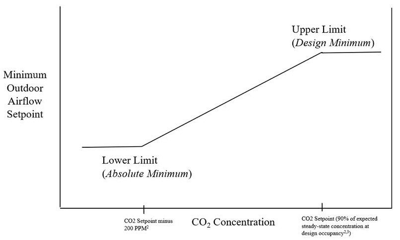
As stated above, there is to be a range of outdoor airflow rates that the minimum ventilation requirement can float between, based on real-time CO2 concentration readings in the return duct, see Figure 3. In DCV, the upper limit of the minimum outdoor airflow set point is to be the design minimum. That is the amount of outdoor air the designer determined is needed to satisfy the ventilation code when the space is occupied at its designed-for occupancy rate (i.e. fully occupied). The lower limit of the minimum outdoor airflow set point is not as easy to define. ASHRAE Std 62.1 sections 6.2.6.1.1-2 and 6.2.6.1.4 set limitations on what that value can be1. But in my experience, it is often the amount of outdoor airflow needed to meet building pressurization requirements that usually is the limiting factor which establishes the value of the lower limit. The lower limit is often referred to as the "absolute minimum".
What I have often run across in my career is a DCV strategy with inappropriate endpoints (upper and lower limits) being used for the minimum outdoor airflow set point. Instead of using the design minimum as the upper limit, it is mistakenly made the lower limit of the set point range. In such instances, the upper limit of the set point range is not established in the programming code, allowing the unit to bring in up to 100% outdoor air during Stages 1 and 4. This common mistake has flipped the script, and now a strategy intended to save energy will only consume more than if DCV was never implemented.
I honestly am surprised I have to dedicate a column to addressing this mistake, but I have seen it too often. I have first-hand examples of designers, temperature controls contractors, and building operators who have had it wrong, but passionately defend their position Tune in next month as I discuss and debunk the common arguments presented by the defenders of the big mistake.
The Consequences
Implementation of a DCV strategy which utilizes the wrong endpoints for the minimum outdoor airflow set point range can have the following consequences if higher-than-designed for quantities of outdoor air are brought in:
- Overextended cooling coil
- It may overextend a cooling coil operating in Stage 4. Temperature and humidity control for the building may be lost.
- Overextended heating coil
- It may overextend a heating coil operating in Stage 1. Temperature control for the building may be lost.
- Coils are places at risk of freezing.
- A correctly functioning freezestat may trip to protect the coils, but such trips compromise the system’s reliability as the AHU will be disabled.
- Increased energy consumption
- Energy waste will occur in Stages 1 and 4.
- Increased steam/water consumption for systems with humidification
- More moisture may need to be added to the supply air stream in Stage 1.
How the Big Mistake Manifests Itself
Sometimes this inappropriate application of DCV is due to a blatant misunderstanding. Other times, it is more subtle mistakes that lead to the wrong sequence being implemented. Some common mistakes made along the way are:
- Incorrectly specified sequences which call out the wrong upper and lower limits on the minimum outdoor airflow set point range.
- Lack of scheduled airflow rates
- I rarely see the lower limit (absolute minimum) scheduled, despite it being required per section 6.2.6.1.5 of ASHRAE 62.1-2022.1
- Lack of direction to the Testing, Adjusting, and Balancing professional
- AHUs can be configured to control for the active airflow set point in a variety of ways. The TAB professional needs appropriate direction on which information they need to determine for input into the control system. This is both true for AHUs who have a customized sequence programmed on a BAS as well as for packaged units who come with a DCV option in the factory controls.
Conclusion
The application of a DCV strategy for AHUs has more pitfalls than discussed in this article. However, the big mistake of using inappropriate end points for the minimum outdoor airflow set point range is a surefire way to ensure this energy savings strategy does just the opposite for your clients. I am continually shocked at how prevalent this mistake is throughout the industry. The intent of this article was to lay out the fundamentals. Next month will teach you to mentally prepare for the difficult conversations you may encounter when pointing out the big mistake.
References:
1 ASHRAE Standard 62.1-2022, Ventilation and Acceptable Indoor Air Quality.
2 ASHRAE Guideline 36-2021, High-Performance Sequences of Operation for HVAC Systems.
3 Lawrence, T. 2008. “Selecting CO2 Criteria for Outdoor Air Monitoring.” ASHRAE Journal (December)


