
District energy is a rapidly expanding sector of the energy market and represents a basic means of saving energy. Community heat pump systems (CHPS) supplying heating and cooling present the opportunity for increasing the thermal efficiency of the households and reducing the greenhouse gases (GHG). This is especially important because conventional fossil fired energy plants have generally reached the limit of thermal efficiency. The main advantages of district energy supply are overall energy conservation, replacement of fossil fuel with “green” electricity, environment improvement resulting from the reduction of fossil fuel burned, and reduction of heat discharged to the atmosphere.
Currently heating and cooling of buildings is one of the biggest sources of GHG. Heat pumps use “free” renewable energy, i.e., thermal energy available in the outside air, the ground or water, and need a small amount of energy to turn the free environmental energy into energy useful temperature levels. The ratio of useful energy delivered by electrical energy needed (Coefficient of Performance, COP) depends mainly on the temperature difference between the free outside source and the required temperature for building space.
There are many different types of heat pumps that could be used, but they all have in common that they use a low temperature heat source. To achieve the economy of scale it is beneficial to use a large environmental heat source to feed a large-scale heat pump-based system (CHPS). This way, the low temperature heat source is used in an optimal way and costs can be spread out over multiple users. Depending on the design of piping network and the selected temperature levels, cooling can be efficiently delivered to the end-consumers as well.
Phasing of energy source development
In evaluating the feasibility of district energy supply, the magnitude and phasing of system load increases (development) are major economic factors. Premature introduction of a base load district energy source or delay in the development of the network piping system will lead to an installation of excess of plant energy capacity and may result in a considerable reduction in the efficiency of the district energy system and increase of energy cost to households. To prevent such situations, two approaches can be used in developing a district energy system.
The first of these is a step-by-step approach. The growth of a district energy system in this case can best be accommodated by starting with multiple low-cost electric-only heating and cooling plants (islands) located close to the energy load centers. As the system grows, and the piping infrastructure is developed, more expensive large base load renewable energy sources can be introduced, with a high-capacity factor already assured. The original electric heating and cooling plants will there¬after serve as peaking and standby units for the large system.
The second approach, considering the relatively long construction time for any major energy source, would be foresight to design the base-load renewable energy plant to accommodate the future district energy load. In the meantime, the CHP plant will operate with partial load and will not be economical. Therefore, only the first approach is discussed in this paper.
CHP system arrangements
CHP systems may supply a combination of space heating, domestic hot water, and cooling loads. These loads usually vary hourly, weekly, or seasonally and require an optimum energy source dispatch to meet the load duration curve. The maximum combined energy generation efficiency is achieved when the CHP plant is designed to match the energy consumption.
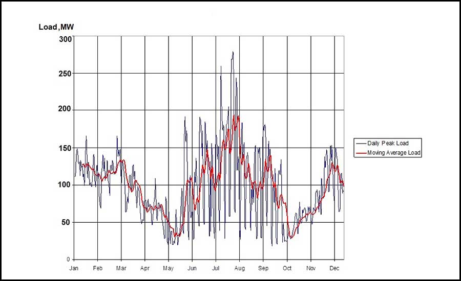
Figure 1 displays a typical hourly district heating and cooling load for an actual downtown system. As one can see from Figure 1 the heating loads from left to right are decreasing toward the spring, afterwards the cooling loads are increasing and decreasing, and the heating loads are increasing again. In district energy practice the combined loads are typically summarized by a load duration curve presented in Figure 2. The load duration curve shows the occurrence hours of every load during the year. To recognize the system economy the renewable energy source should be designed to supply substantial heating and cooling loads most of the year (base load operation). This is schematically indicated by the horizontal line on Figure 2. It is economical to supply the peak and back-up loads by low capital cost electric resistance boilers already installed at the first development stage. The optimal capacity dispatch coefficient for the base load district renewable plant is determined by economic tradeoffs, but it is typically between 50 and 80% of the peak system load.
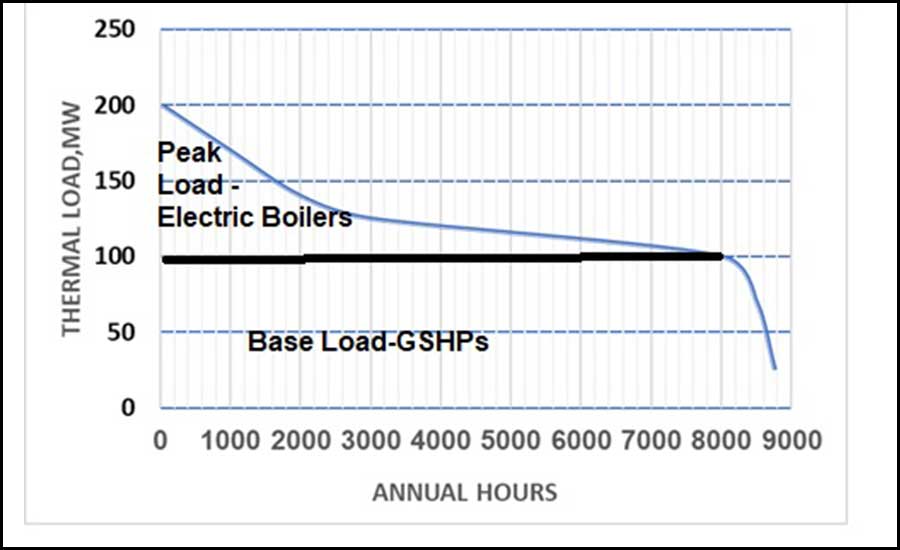
Use of electric boilers and chillers for the first district energy development stages allows to reduce the initial capital investment and development cost and coagulate more customers into district energy clusters. While the individual community clusters (islands) grow, it is possible to develop more capital-intensive renewable energy sources (like ground source heat pump) supplying base load heating and cooling (horizontal line in Figure 2). After development of optimum number of heat load clusters, they are connected with piping to the base-load CHP plant. The renewable energy source will have much higher energy efficiency (for example, for GSHP system COP close to 4-5) while the electric boilers will supply loads with COP close to one.
Optimum energy distribution
The main components of a district energysystem include the energy production source, underground energy distribution (hot or chilled water piping), energy transfer stations, and metering devices at the customer entrance terminals.
The piping distribution systems (for large systems can represent close to 50% of the total CHP system investment cost) are closed loop systems with two-pipe arrangement (for district heating), and four-pipe arrangement (for district heating and cooling). The economics of the energy distribution system depends on the distance and load concentration. The reliability of an underground piping system is determined by the following factors: quality of anti-corrosion protection, average annual water temperature in the piping network, type of installation, site hydrological and soil conditions, and the condition of adjacent underground soil, water, and sewer systems. It is of major importance, if not mandatory, that the piping installation contractor be highly qualified and capable of closely implementing the requirements of the installation specification. It is equally important to provide careful supervision of the contractor's work. Underground distribution piping systems should be designed to achieve efficient long-term operation (30 to 50 years) with the following general characteristics:
- Minimum heat losses.
- Casing resistant to ground water infiltration, mechanical or structural damage, corrosion, and other causes of deterioration.
- Capability to sustain the rated pressure and temperature for all operating life.
- Insulation that is durable and compatible with the fluid temperature, and that can accommodate expansion of the piping system.
As the use of heated and chilled water became popular, so did more advanced piping materials. While district steam systems still exist in some large cities and campus complexes, modern district hydronic systems using hot and chilled water are being applied in new applications. In the last 20 years district heating piping was operatedattemperaturelevelsupto210F (so-called3rdgenerationdistrict heating). In new low temperature district heating the network supplytemperatureisreducedtoabout 120-140F or evenless(4th generationdistrict heating).The low temperature district heating piping canreduceheatlossesinthenetworkbyupto 75% compared to the current system design.
Bonded systems with steel carrier piping
Typically, the district energy piping is installed under city or campus streets. The piping network transmission lines are connected to the source of energy. The transmission trunks supply smaller distribution piping which feed individual buildings with heated or chilled water. Each building is equipped with an energy meter that measures water flow rate and supply and return temperatures to calculate customer energy consumption for billing purposes.
The bonded systems consist of a steel carrier pipe, insulation and an outer casing or jacket in contact with the insulation. The jacket or outer casing can be PVC, cement pipe, polyethylene, polypropylene or FRP. The jacket provides a water barrier to prevent underground moisture from entering the insulation. Field joints are similarly protected. The insulation is usually polyurethane. The piping systems are typically prestressed eliminating the need for expansion joints or loops. For bonded systems with plastic casings, special care must be taken during installation not to damage the casing. The pipe must be laid on a bed of rock-free sand and completely covered with sand so the casing will be protected from punctures.
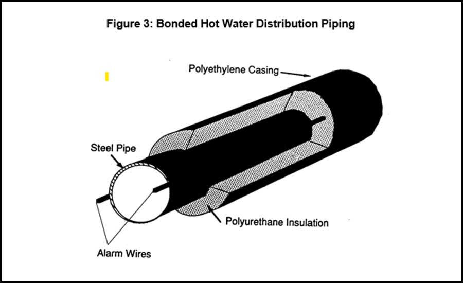
The bonded system has no air gap between the insulating layer and the outer casing, and all components expand as a single system. The system has achieved popularity for its enhancement of the manufacturing plant efficiencies and ease of export from the plant. The improved technology offers lower installation and maintenance costs. The hot water piping system consists of a thin wall carbon steel carrier surrounded by polyurethane insulation and encased with a polyethylene jacket (Figure 3).
This construction features excellent resistance to ground water infiltration and a built-in leak detection system. If moisture enters the jacket and saturates the insulation, the entrained water completes an electrical circuit triggering an alarm. The leak can be located accurately by measuring the resistance to ground, minimizing excavations and downtime. Another innovation in low temperature hot water systems is the method for accommodating thermal expansion. The limited temperature rise experienced in low temperature water systems allows use of a technique that exploits the mechanical elasticity of the steel carrier pipe. The procedure requires preheating the piping to a designated temperature, encouraging its free mechanical expansion.
In the next step, pipe fitters “freeze” the piping in this position through specially designed fittings or through backfilling the trench over the heated section. As the system is returned to ambient temperatures, a tensile pre-stress is developed in the pipe as it attempts to contract to its original length. When the system temperature is elevated to final operating conditions, a positive compressive stress is induced in the piping as the steel expands. Owing to the compensating tensile pre-stress however, the stress at temperature is well below the stress that is allowable by code.
These systems offer the following advantages:
- Reduced Installation Time: Since the system is prefabricated, welding, joint insulation and joint enclosure techniques are pre-engineered, reducing time in the field.
- Superior Protection from Water Ingress: With a durable polyethylene casing and advanced jointing, these systems provide lasting protection from ground water.
- Reliable Design: System components are designed to be installed and tested to reduce field errors and future problems.
- Thermal Compensation: By taking advantage of the elastic characteristics of the steel carrier pipe at these temperatures, no expansion loops or expansion joints are required for this design that reduces component and installation cost.
- Built-in Leak Detection: These systems have built-in leak detection and locator systems that indicate problems that need prompt repair. Leaks are located accurately, quickly reducing excavation time when searching for leaks.
Experience of using plastic carrier pipes
Hydronic heating and cooling technologies are constantly evolving, and hydronic carrier distribution piping is one of the primary applications for the plastic piping materials, providing economical, safe, sustainable, and reliable transport of heated and chilled water, without corrosion, or environmental issues associated with traditional metal materials. Plastic piping materials have been approved for hydronics in mechanical codes across USA and Canada, including the Uniform Mechanical Code (UMC), International Mechanical Code (IMC), the International Residential Code – Mechanical (IRC-M), and CSA B214 (Installation Code for Hydronic Heating Systems) (Ref.2).
The major advantages in the utilization of plastic carrier piping for district energy compared to the carbon steel are as follows: elimination of electrochemical corrosion problems, reduction of pressure drop and pumping power, reduction in the insulation thickness required, and reduction in the installation cost. Typically, cross-linked polyethylene piping is used. The system has the following advantages: high corrosion resistance, high piping strength, substantial reduction in piping joints, low friction losses and subsequent reduction in pumping power, elimination of expansion devices, reduction in piping weight, easy to handle and install. The cross-linked polyethylene piping in sizes up to 1 in. can be utilized for temperatures up to 200F and pressures up to 145 psi. Pipes with sizes up to 4 inches may be used in systems with temperatures up to 200F and pressures up to 85 psi. The pipe is manufactured in lengths of both 150 and 300 ft. The pipes up to 3 in. in diameter are rolled up in bundles which can usually be carried by two men. Utilization of cross-linked polyethylene pipe in low temperature district systems results in cost reductions of up to 50 percent over conventional carbon steel conduits.
Novel methods for accommodation of piping thermal expansion are developed and utilized widely such as sinusoidal curve pattern designs and piping prestressing techniques. In these systems, expansion devices and loops are eliminated from the network resulting in the reduction of installation costs.
Plastic carrier pipes for district heating systems offer a wide range of benefits over steel materials resulting in installations which are simple, quick, and cost effective with good long-term performance. The advantages include:
- Supplied in coils (typically close to 1000 ft in length) which minimizes the number of joints needed compared to 40 ft straight lengths for steel pipes and capability of special techniques such as ploughing in, pulling through and horizontal direction drilling.
- Flexibility allowing the pipe to be routed around other services and obstacles without installing additional joints and capable of withstanding ground movement in service.
- Lightweight offering the possibility of installation without mechanical handling equipment.
- Easy to join using standard site equipment and techniques.
- Elimination of expansion bends, used to accommodate significant expansion and contraction due to temperature changes for steel piping.
- Corrosion resistant and smooth bore extending lifetime and minimizing deposit build up inside the steel pipes.
- Elimination of leak detection systems, typically used in district systems to monitor and minimize loss of heat due to corrosion of the inner pipe.
- Trenches are narrower as no additional space is required for welding around the pipes.
- Smooth wall, excellent flow characteristics reducing pumping costs.
- Flexibility preventing pressure surges and water hammer, reducing pressure spikes, and extending equipment life.
- Do not support biofilm growth, reducing the need for water treatment chemicals such as corrosion inhibitors.
- With clean and flame-free joining systems, the risk of fire is reduced.
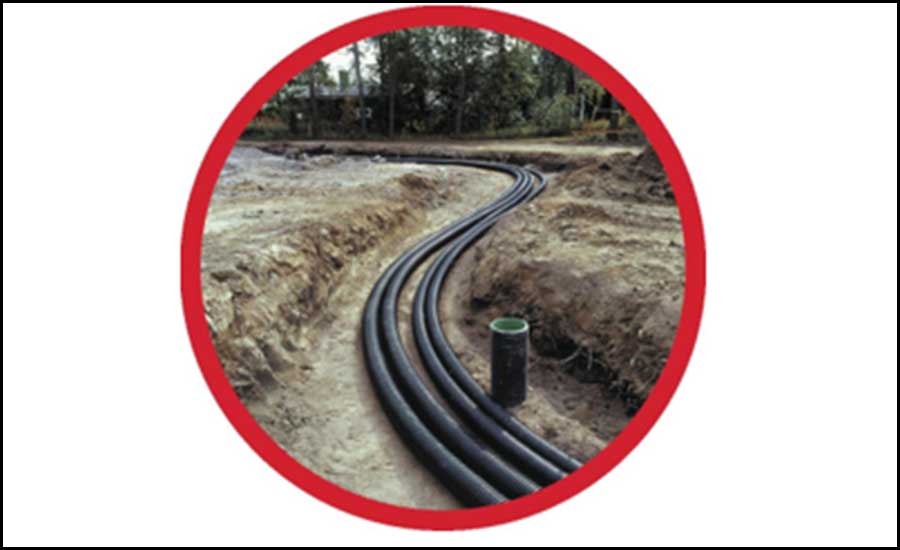
Community heat pump-based district systems are good applications for plastic carrier piping. Many plastic piping materials are rated for operation at 180F, whereas others (e.g., HDPE) are better suited for chilled water applications. Because flexible plastic piping systems are often supplied in long continuous lengths, many joints and connections can be eliminated. Further time savings are realized when these relatively flexible pipes are easily bent around obstacles (Figure 4).
Chilled water distribution
Many construction techniques used for hot water distribution are also applicable to chilled water distribution. Several factors, however, allow the use of alternative construction practices and materials that reduce project costs. Since chilled water distribution temperatures are about 40F a variety of piping systems can be used. Plastic and fiberglass piping has been used with some success but is usually selected in diameters less than 12 inches. The piping is insulated if the economics are justified. In many parts of the country, ambient soil conditions approach the temperature of the chilled water system and insulation is considered unnecessary. The bonded conduit systems previously described for hot water systems have also been used for chilled water distribution.
Since distribution of chilled water is similar to a municipal water supply, some district chilled water systems have used the same piping technology. When large piping diameters are required, ductile-iron pipe is economical (Ref.1). This pipe is highly resistant to ground-water corrosion and if properly constructed the joints are water-tight, the district cooling system requiring minimal makeup.
Supply-to-return temperature drops for chilled water systems are generally limited to 15F to 20F.Serving the load with lower temperature differential necessitates larger flow rates and piping sizes. Further increases in the temperature drop can be achieved through ice-storage based systems.
Chilled water systems generally operate between 40F and 60F, within the temperature limitations established for plastic piping materials. Their advantages include the elimination of corrosion due to ground water infiltration and a reduction in weight. They are not suited for installation under significant vehicular loads unless their reduced strength is compensated for by a greater burial depth. Limitations on flow velocity and potential damage from water hammer must be considered.
While insulation is not as critical for chilled water piping as it is for hot water systems, it is commonly provided. It is particularly common in prefabricated piping installations. In field fabricated installations, insulation is generally applied to the supply line; the return line may not be insulated. The most common insulation for chilled water systems is polyurethane. Its excellent insulating properties, ease of application, exceptional load bearing characteristics, and resistance to water absorption make it ideal for underground service. Generally, polyvinyl chloride or polyethylene jacketing is employed to protect the insulation mechanically and to form a vapor barrier against condensation.
Since the chilled water system is maintained at a temperature that approaches the temperature of the surrounding ground, thermal expansion is not significant. These two advantages permit designers to use less expensive jointing techniques. Slip—on and bell and spigot joints significantly reduce labor costs as compared to welded pipe construction. As plastic materials are not susceptible to water—induced corrosion, the special sleeve that protects the joint in steel systems is not required. However, elbows, pipe reducers and valves must be supported by concrete thrust blocks to protect the joint and system from movement due to internal pressure. Thermal stresses are greatly reduced in chilled water systems due to their near ambient operating temperatures. This significantly reduces the need for expansion loops or bellows devices. Some manufacturers claim, with slip—joint construction and the inherent flexibility of the piping material itself, that no compensation for thermal expansion is required at all.
When it comes to range of diameters, polymer systems are limited in diameters up to 12 inches. Larger district systems can use a hybrid of steel and polymer pre-insulated pipe systems with steel systems used for transmission lines and the distribution network and smaller connections being made with flexible plastic systems. Typically, the smaller diameters of polymer pipes are delivered to site on a roll, resulting in narrower trenches and having the snake their way around obstacles. Some of the piping (PEX-AL-PEX) is equipped with oxygen barrier eliminating the transmission of oxygen from the atmosphere through the tubing wall. This is intended to prevent oxygen from dissolving into the hydronic fluid and potentially causing corrosion in any ferrous components within the piping system.
Plastic pipes do not erode or corrode, preventing the expensive damage that occurs when metallic pipes leak. Plastic pipes also do not experience scale build-up, which can impede flows, increase pumping costs, and reduce system efficiency. The pipes are typically joined using heat fusion which physically welds the components into a monolithic piping system. Mechanical compression fittings are also available. These joining techniques eliminate the use of flame for constructing the piping system.
The mechanical jointing methods are much faster than welding, use simple installation equipment, and require less space in the trench permitting narrow trenching to be used. They are more forgiving of slight pipe misalignment, and the flexible nature of the pipe means there is no need for on-site fabricated adaptors to circumnavigate obstacles in the ground. As with all jointing, good practice and working strictly in accordance with manufacturer’s guidance will offer a watertight system which can be verified by pressure testing. For efficient and long-lasting network performance, all below ground joints require insulation to reduce heat loss. The mechanical jointing methods used with polymer pipes are provided with simple to use insulation sets.
REFERENCES
1.Oliker, I and Clark, M. Indianapolis Might be a Template for Cities Around the World,25 years of progress suggests benefits that could be replicated elsewhere. DISTRICT ENERGY, Spring-Summer 2022.
2.Plastic Pipe Institute.


