
Bypass pipes, accompanied by a three-way control valve, are often seen in hydronic systems at both served loads (e.g., reheat coils) as well as at primary equipment (e.g., cooling towers).
Reasons for utilizing a three-way control valve and bypass pipe at served loads include:
1. To ensure a path of flow is provided so as to not excessively throttle, or even deadhead the pump during low loads.
- Constant-speed hydronic systems aim to keep a relatively constant, total system flow. Thus, most loads are served by three-way control valves with an associated bypass pipe.
- Variable-speed hydronic systems utilize the bypass to provide a path for minimum system flow during low thermal loads. A small percentage of the served loads are served by a three-way control valve for this purpose, while most are served by two-way control valves so that differential pressure in the system will build during part-load scenarios and the pumps will slow down (and thus save energy).
2. Ensure appropriate temperature water is available “on-demand” when the three-way control valve begins to open.
- This concept often drives design engineers to select remotely isolated loads, or very critical loads, for the relatively few three-way control valves they include in a variable speed hydronic system design.
Reasons for utilizing a three-way control valve and bypass pipe at primary equipment include:
- Ensure a path of flow is provided as to not excessively throttle or even deadhead the pump during low loads.
- Provide a means for low-load temperature control (e.g., when the cooling tower is producing cooler-than-desired supply temperature).
The above reasons listed for bypasses are widely accepted and understood. What is widely misunderstood, is the critical importance of the balancing valve in the bypass pipe. Such a balancing valve is highlighted in Figure 1.
THE EFFECTS OF UNTHROTTLED FLOW THROUGH THE BYPASS
The primary purpose of the balancing valve is to throttle flow when the three-way control valve opens to the bypass pipe. If no balancing valve exists, excessive flow will be sent through the bypass. For example, if you have a three-way control valve serving an air-handling unit’s cooling coil that has a 10-foot pressure drop at a design flow of 100 gallons per minuite, then an unthrottled 3-inch-diameter bypass pipe only 5 feet in length would be a short-circuit, allowing for substantially more than 100 gpm to pass through it.
The excessive flow that can result when the bypass pipe is not throttled by use of a balancing valve can have differing effects depending on the system configuration.
- In a constant-speed hydronic system, it is very common for all loads to be served by a three-way control valve. Omitting the balancing valves in the bypass pipes of those loads provides the pump with a much less restrictive path for flow during part-load scenarios. As a result, the pump will push more flow and operate in an undesirable region of its pump curve.
- In variable-speed, primary-only hydronic systems, unthrottled flow through the bypass will increase flows observed during part-load, which will drive up pump energy consumption (the opposite of the intended goal of going variable speed in the first place).
- In constant-speed, primary/variable speed secondary systems, unthrottled flow through three-way control valve bypasses can drive up secondary flow beyond primary flow. This can result in degrading secondary supply temperature, or premature staging of primary equipment, depending on the staging strategy of the primary equipment1.
Some additional, undesirable effects caused by unthrottled flow in the bypass are listed below:
1. Unstable control of the three-way control valve
- For example, in an AHU, a three-way control valve may be modulated to maintain discharge air temperature at setpoint. As the coil’s thermal load decreases and the control valve modulates flow into the bypass pipe, a rush of water flows through it, drastically reducing flow through the coil. This may result in controllability issues and making the job of tuning that control loop much more difficult for the temperature controls contractor. The unthrottled path of flow through the bypass reduces the turndown ratio of the control valve.
2. Excessive velocity
- Unthrottled flow through the bypass can result in excessive velocities being realized. Excessive velocity of water through pipes can prematurely erode pipes and other hydronic specialties, as well as put certain components at risk of producing cavitation.
3. Excessive noise
- Excessive velocities can bring excessive noise, which may be disruptive and unsettling to occupants of the facility.
4. Starving of adjacent loads
- If a coil served by a three-way control valve is at part-load, and its bypass is unthrottled, the collective flow associated with that coil is much higher than what it was designed for. This may steal flow away from adjacent coils during such situations, potentially compromising those adjacent coil’s ability to provide temperature control.
5. Energy waste
- Generally speaking, pushing more system flow means consuming more pump energy. In a constant-speed pumping operation, if bypass flow is unthrottled, the duty point of the pump moves further to the right on the pump curve as the system’s thermal load is reduced. This will result in increased pumping power consumption. See Figure 2 for details.
- In variable-speed pumping operations, unthrottled flow though the bypass may limit the amount of savings seen during part-load scenarios.
6. Cavitation concerns
- As the pump operates further to the right on its pump curve, the risk for cavitation increases as the net positive suction head requirements increase. See Figure 2 for details.
7. Unexpected return water temperatures
- When water flows through a bypass, that short-circuited water at the supply temperature will eventually mix with water that has flowed through active coils. The greater the extent of unthrottled flow, the closer the resultant return water temperature will be to the supply temperature. Too high of heating hot water return temperatures may reduce a condensing boiler’s combustion efficiency. Too low of chilled water return temperatures, or too high of heating hot water return temperatures, may have impacts on systems which attempt to utilize heat recovery chillers. Such an example will be detailed in Part II of this series.
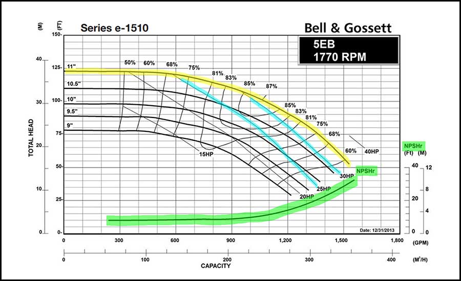
Figure 2: Pump performance data. Net Positive Suction Head requirements (NPSHr, highlighted in green) and power consumption (blue) increase the further to the right the pump operates on its pump curve (yellow).
Images Courtesy of Bell and Gossett
ESTABLISHING BYPASS PIPE FLOW RATES
Generally speaking, the following are rules of thumb for establishing the appropriate flow rate for which testing, adjusting, and balancing (TAB) professionals should be setting the bypass pipe’s balancing valve to.
Constant-speed systems’ served loads:
- Set the balancing valve so that when the three-way control valve is fully open to the bypass, the scheduled flow rate through the coil is achieved. There may be some benefits to going slightly less than scheduled coil flow as well.
Variable-speed systems’ served loads:
- The sum of the bypass flows for the coils selected to be served by three-way control valves should be no higher than the minimum system flow requirements. Those minimum flow requirements may be established by either the primary equipment (boiler, chiller, etc.) or by the pump itself. For example, if the minimum system flow is 20 gpm, and the two coils selected for three-way control valves have relatively close design flow rates, then set each of the bypass’ balancing valves to 10 gpm. One could even further limit those flows on the assumption there must be some flow going through coils somewhere in the system.
- If a three-way control valve is only used to provide appropriate temperature water “on demand,” a very small amount of flow will provide this capability.
For bypasses around primary equipment:
- Set the balancing valve so that when the three-way control valve is fully open to the bypass, the scheduled flow rate through the primary equipment is achieved. This is both to limit flow at part-load and for controllability of that valve. For example, the balancing valve on a bypass line of cooling tower should be set to have a pressure drop equal to the height of the cooling tower2.
WHY AM I TALKING ABOUT THIS?
There is widespread indifference in this industry to the importance of the bypass pipe’s balancing valve. It may be a fundamental lack of understanding as to why balancing valves in the bypass pipes are needed. I would estimate that 90% of the buildings I have worked in fall into one of the following categories when it comes to balancing valves being installed and properly set in the bypass pipes of a hydronic system:
- Bypass balancing valves are not in the design.
- Bypass balancing valves are shown in the design but are not installed.
- Bypass balancing valves are shown in the design, are installed, but are not balanced.
- Bypass balancing valves are shown in the design, are installed, but are not properly balanced (often due to a lack of direction from the design engineer).
CONCLUSION
Commissioning providers are uniquely positioned to educate the industry and break us out of the cycle of neglect when it comes to the bypass pipe’s balancing valve, as well as to ensure their clients are not plagued by the nuances of unthrottled flow through the bypass pipe. The following are the steps to combat this trend in a new construction project:
- Figure out the designer’s reasoning for the three-way control valves.
- Ensure a balancing valve is included in piping details. Merely showing an isolation valve is not sufficient.
- Ensure direction is provided for what flow rate the valves are to be set for.
- Confirm TAB professional understands what is required during coordination meetings.
- Inspect the bypass valve after TAB is complete to ensure it isn’t left wide open.
Part II of this series will provide several examples from recent projects that aim to convince readers of the criticality of these valves.
References
1Taylor, S. T. 2002. Degrading Chilled Water Plant Delta-T: Causes and Mitigation, ASHRAE Transactions 108 (1).641-653.
2Energy Design Resources. 1999. CoolTools™ Chilled Water Plant Design Guide.


