
The way we control the speed of fan motors or pump motors has tremendously changed in the past two decades with the introduction of variable-frequency drives (VFDs), aka variable-frequency controllers (VFCs). In the distant past, convincing an owner or a contractor to have VFDs control fan and pump motors required a detailed return-on-investment analysis. Today, thanks to their relatively low cost and to the code-mandated energy efficiency requirements of HVAC fan and pump systems, it would be unusual to not have VFDs control fan motors and pump motors. To ensure its safe operation, a VFD should also be listed and labeled by the Occupational Safety and Health Administration's Nationally Recognized Testing Laboratory (NRTL) as a complete unit, capable of providing self-protection and also capable of providing protection for the motor it controls.
When applied to the control of fans and pumps and when controlled properly by a building automation system (BAS), the VFDs have the potential of saving significant amounts of energy over the life of the motor.
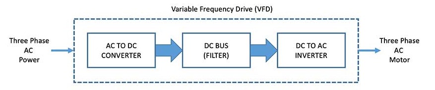
As shown in Figure 1, a VFD has three main components: an AC to DC power converter; a DC filter, and a DC to AC pulse-width-modulated inverter that is factory built and tested in an enclosure with integral disconnecting means and overcurrent and overload protection. These three main components can then provide variable-speed control of one or more three-phase induction motors by adjusting the output voltage and frequency.
Two Methods of Control
Depending on the application, typically there are two methods by which a VFD can control the speed of an electric induction motor: the vector control method and the volt/frequency (V/Hz) method.
The vector control method is an advanced control technology that utilizes several complex algorithms and encoders to provide precise motor control. Precision as low as one revolution per minute (rpm) can be achieved. The encoders eliminate any error generated during feedback response and enable the VFD to react quickly.
Additionally, vector control allows torque regulation, high-starting torque, and higher low-speed torques. It also enables the VFD to react to high-torque conditions to prevent equipment damage. Typical applications include washing machines, extruders, high-speed spindles, and smart conveyors.
The V/Hz control is a widely used method in the HVAC industry. When there is a request for a change in the speed of the motor, the V/Hz control method adjusts the VFD’s output voltage and frequency curve, which in turn serves as an input to the motor. This method allows torque adjustments for improved efficiency in the case of variable torque applications.
It is important to note that the control of the speed of a motor using the V/Hz method is not precise; this method allows the actual speed measured in rpm to slightly drift from the targeted speed set point.
A typical BAS sequence of operation for the control of a chilled water pump serving a large, chilled water plant and designed to deliver 2,000 gallons per minute (gpm) of chilled water to various air handling units could be as follows: The BAS shall modulate the speed of the pump motor to maintain a differential pressure set point, as sensed by the differential pressure sensors installed between the supply and return chilled water piping. The differential pressure set point shall be maintained between maximum and minimum pressures; the maximum pressure limit is the pressure required to provide full flow to all loads simultaneously and the minimum pressure limit is the pressure correlating to the lowest speed the pump is allowed to be operate at (based on minimum chilled water flow and minimum pump flow).
The goal of the sequence of operations described above is to ensure that chilled water is delivered to the air-handling units as needed, regardless of the speed at which the motor is required to operate to deliver the chilled water.
Overspeed and Underspeed
However, just because the BAS does not “care” about the speed at which a motor is required to operate in order to achieve a certain goal (e.g., chilled water pressure set point, supply airflow set point, etc.), it doesn’t mean that the BAS can underspeed or overspeed a motor. Rated horsepower (hp), brake horsepower (bhp), torque, efficiency, etc., are all motor performance factors that need to be considered when directing a VFD via a BAS to overspeed or underspeed a motor.
The rated hp of a motor is the work produced by the motor at rated voltage and amps while BHP is the actual work delivered at the shaft of the motor, when accounting for losses (i.e, motor slip, friction, etc.).
The slip of an electrical induction motor could be defined as the difference between its synchronous speed and asynchronous speed; the synchronous speed of the motor is the rated speed at a nominal voltage (i.e 208 V, 460V etc.) and 60 Hz while the asynchronous speed is the actual speed of the motor when the voltage and frequency parameters are changed (by the VFD).
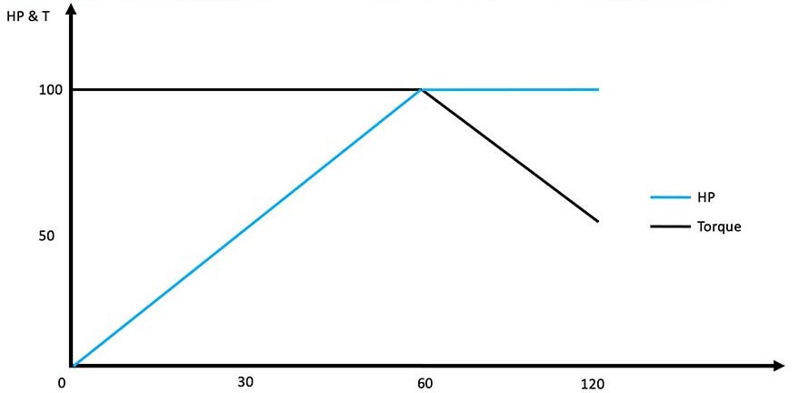
The relationship between torque and hp is defined by the formula: HP = (T x RPM) / 5,252. Figure 2 shows the relationships between the speed of an electrical induction motor, torque and hp.
The Importance of Voltage
When the motor is operated above 60 Hz, the horsepower becomes constant, and the torque starts to decrease. The continued operation at decreased torque results in overloading of the motor.
In order to maintain a constant torque, availability of voltage is an important factor. When the operating frequency rises higher than the standard frequency, i.e 60Hz, maintaining constant torque cannot be possible since the VFD’s voltage cannot exceed the input voltage. In other words, the motor will not be able to produce more BHP just because it is operating at a higher rpm.
When the motor is operating at higher speeds, while delivering less torque, there is an increase in the risk of having vibrations occurring at the rotor’s shaft, which in turn could cause an increase in mechanical and thermal stresses on the motor; these additional thermal stresses could significantly reduce the useful life of the motor bearings.
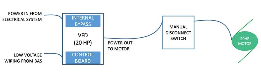
Figure 3 shows a sample wiring diagram of a VFD controlling one 20 hp electrical induction AC motor; the hp rating of the VFD must not exceed the hp rating of the motor. In the example shown in Figure 3, the VFD is provided with an internal bypass function that safely transfers the motor between power converter output and bypass circuit. When the bypass function is activated (either manually or automatically), the VFD is capable of stable operation (starting, stopping, and running) with the motor completely disconnected from the power converter. It is important to note that additional considerations of electrical system parameters and associated code requirements are required when specifying a VFD with an internal bypass function. The bypass function of the VFD must permit the safe troubleshooting and testing of the VFD when the VFD is both energized and de-energized and while the associated motor is operating in bypass mode.
Manual and Automatic Operation
Typically, the internal bypass function of a VFD can be achieved via two modes: manual operation only and automatic operation.
In the manual operation bypass mode, the user activates the mode manually. In this instance, the transfer between the power converter and the bypass contactor, and the subsequent retransfer, is only allowed when the motor is not rotating.
In the automatic operation bypass mode, the user activates the mode either locally or remote (via a BAS command). In this instance, the transfer between the power converter and the bypass contactor, and the subsequent retransfer, is done via a user interface or automatic-control system feedback.
When the motor is not located within sight of the VFD, additional means of disconnecting power to the motor are required to be provided within sight of the motor. Typically fused or non-fused disconnect switches are used to accomplish this task. This approach is code required and is done to eliminate the risk of having a remote operator energizing the motor (either at the VFD or remotely via a BAS command) while the motor is being locally serviced by a service technician. Further, the operation of the VFD must be hardwire interlocked with the position of the associated fan motor disconnect switch such that if the manual disconnect switch is in the off position, the VFD is not allowed to energize the motor.
As shown in Figure 4, a VFD can also control multiple motors; this is typically done when air-handling units (AHUs) are provided with a fan array system.
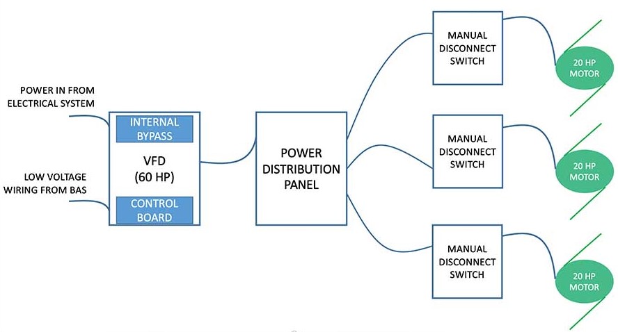
In this scenario, all fans will be controlled as one single fan and the nominal HP rating of the VFD must be equal to the combined HP rating of all motors that the VFD controls. From a controls perspective, it is important to note that the only way for the VFD to control multiple motors at the same time is by using the Volts per Hertz method. Further, it is the recommendation of these authors to have a Power Distribution Panel (PDP) located between the VFD and the motors. The PDP should include individual fan manual motor protectors, alarm relay, motor overload and individual disconnecting means to disable power to each individual fan in the fan array without disrupting AHU operation for the remaining fans in the fan array.
If the motors are not located within sight of the PDP, additional disconnect switches are required to be provided within sight of the motors. These authors also recommend having the operating mechanism on the disconnect switches to be quick-make, quick-break, and shall not be capable of being restrained by the operating handle during the opening or closing operation.
Flying Start and Dynamic Braking
To minimize nuisance alarms from the VFDs or unnecessary shutdowns of air-handling units and pumps, the VFDs should also be provided, as a default, with two additional functions: flying start and dynamic braking.
When the flying start option is activated, the VFD senses that the motor is already rotating, and it will automatically select the correct output frequency to start controlling the already rotating motor. This function is extremely important when VFDs are controlling fans in a fan array system. If a fan motor within the array is not energized by a VFD while the rest of the fans are off, the fan itself is still rotating.
Dynamic braking is a control method used to dissipate the excess energy that is generated when the motor controlled by the VFD is rapidly slowed or stopped. This is because when a VFD tries to rapidly slow down or stop the motor, the motor becomes a generator of energy, sending energy back to the VFD. An external brake resistor together with an internal brake chopper are typically provided by the VFD manufacturer to absorb the extra energy. Once absorbed, the extra energy is dissipated as heat into the surrounding space.
From an integration perspective, the VFDs are typically integrated into the BAS via hardwired connections and/or a software connection. Figure 5 shows a sample BAS VFD controls diagram.
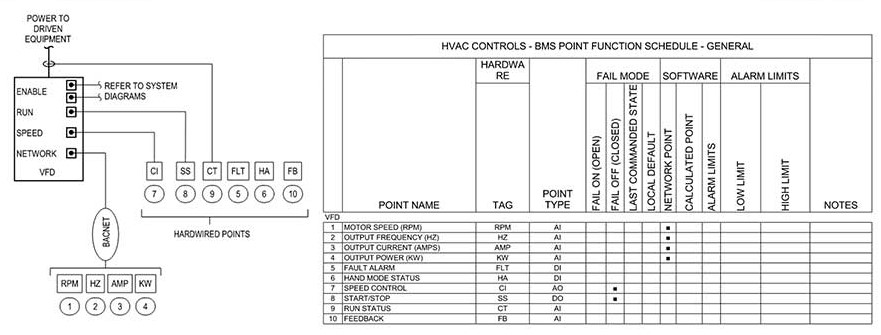
To ensure that the BAS communicates with the VFD as fast as possible, these authors recommend hardwiring a minimum number of controlled points, while other control points can be accessed by the BAS via a BACnet connection.
Hand-off-auto (HOA) capabilities are typically provided as a part of the VFD through its keypad interface. When the VFD is in the hand mode, the user controls the speed of the motor locally by manually adjusting the Hz setting. When the VFD is in off mode, the motor does not rotate. When the VFD is in the auto mode, the BAS controls the motor. In the case of AHUs, safety switches like high static pressure switches, freezestat, smoke damper are hardwired to the VFD’s safety interlock contacts while AHU isolation dampers are typically wired to the VFD’s "run permissive" contact. Depending on how they are wired (normally open or normally closed) and upon their activation, both sets of contacts will prevent the VFD from energizing the motor or motors.
Increased Reliability
To increase the reliability of the assembly (VFD + Motor), these authors also recommend the installation of current transducers (CTs) on the power wiring between the VFD and the motor. By measuring the amperage drawn by the motor, the CTs are used to determine the actual status and loading of the motor and compare said status with the commands given by the BAS. For example, if the BAS commands the VFD to turn on the motor and rotate the motor at a speed of 30 Hz but the amperage drawn by the motor, as measured by the CTs, is zero, it is could be an indication that the motor has failed to start.
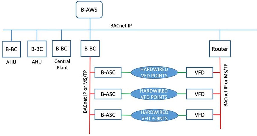
To increase the resiliency of the system and as shown in Figure 6, these authors recommend integrating the VFDs into the BAS via a separate dedicated network loops. One loop is dedicated only to network points and another loop is dedicated only to hardwired points. In this scenario, should the BAS lose communication with one of the network loops, the BAS could continue using the remaining network loop and still have full control over the VFDs.
The latest VFDs models are provided with enhanced capabilities and network points that allow a facility manager to monitor the energy consumption of the HVAC systems in real time; current draw, actual RPM, power demand (in kW) are just some of the network points, typically accessed via a BACnet communication protocol, that can be used of monitoring and trending the energy performance of an HVAC system that uses VFDs to control fan motors and/or pump motors.


