
Moist air in buildings makes a thriving environment for common allergy triggers, such as dust mites, mold, and mildew, as well as common bacteria and other pathogens. High humidity can also have negative impacts on the longevity of building materials. Therefore, it’s important to have a means to dehumidify building air and maintain adequate relative humidity levels within a building. Over the decades, the most basic methods of humidity control have greatly evolved, and with the advancement of modern technology, even more have been discovered. With a robust array of design options, i.e., enthalpy wheels, desiccant wheels, etc., combined with energy costs and the rising concern for climate change motivating energy efficiency, designers are often tasked with the challenge of deciding which dehumidification methods best suit their projects’ needs.
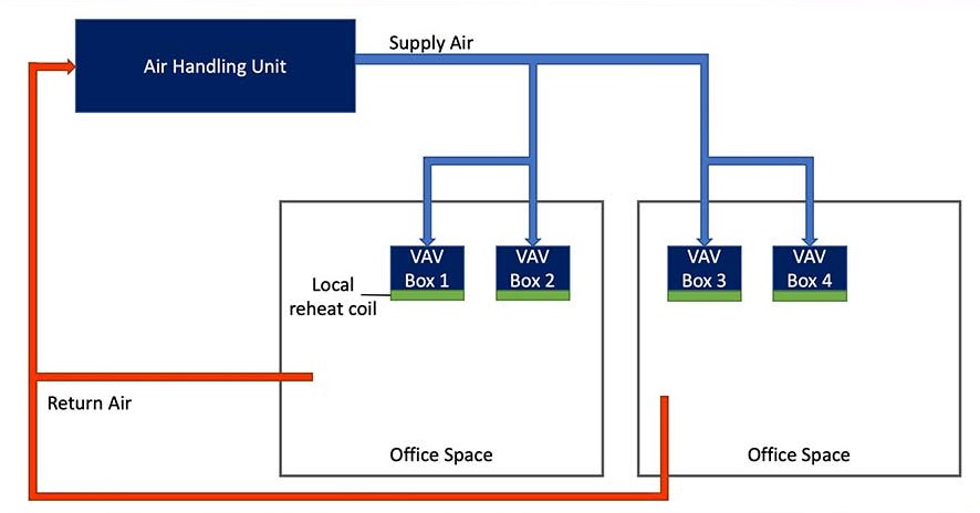
Figure 1 shows a typical design of an office-type building. An air-handling unit (AHU) conditions the air before sending it to local variable air volume (VAV) terminal units. These terminal units are typically provided with a reheat coil, which, in general, serves two purposes: prevent the spaces from being overcooled and serve as the main source of heating for the space.
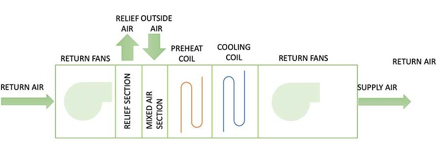
Typical indoor design conditions for office-type spaces are 75°F dry bulb (DB) and 50% relative humidity (RH), while a typical AHU configuration is shown in Figure 2. It is important to note that, regardless of the type and configuration of the AHU, the supply air temperature (SAT) out of the AHU needs to be on or below the sensible heat ratio (SHR). This is to ensure the air being delivered into the spaces is dry enough to compensate for the humidity gain within the space. This is where the risk of overcooling the spaces can increase significantly, in particular when the spaces are not fully occupied.
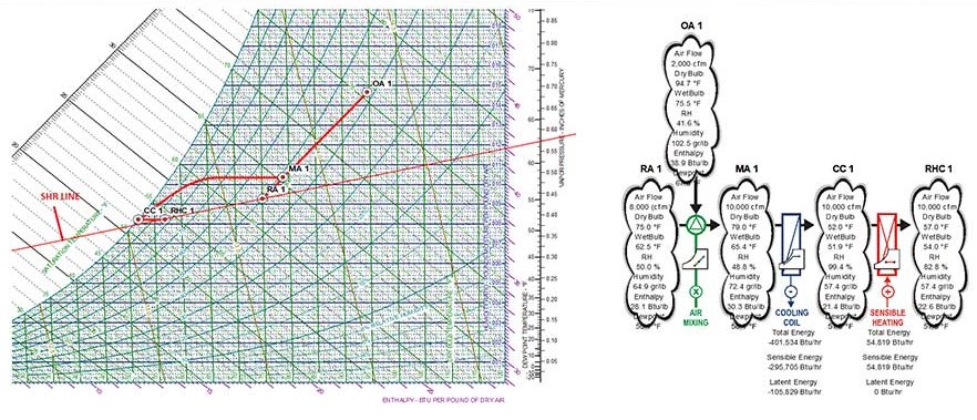
The cooling coil leaving air temperature (LAT) needs to be low enough to remove moisture out of the airstream, yet the space supply air temperature needs to be warm enough to not overcool the spaces. Figure 3 shows a psychrometric analysis of the system shown in Figure 1. In order to simplify the psychrometric chart, the fan heat gain has not been modeled. Further, during low load conditions within the spaces and while in cooling mode, the discharge air temperature out of the terminal units that are provided with reheat coils could vary between 55° and 75°.
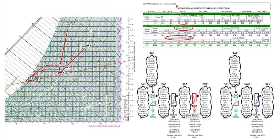
Another design aspect that needs to be considered when designing an HVAC system’s dehumidification operation is the sizing of the cooling coil. A natural tendency could be to size the cooling coil for the ASHRAE annual cooling criterion and assume the system will operate properly; however, the design engineer must perform a psychrometric analysis of the system using the ASHRAE annual dehumidification criterion. Figure 4 shows a comparison of the energy required to dehumidify the air based on the two conditions, i.e., annual cooling criterion versus annual dehumidification criterion. As shown, the energy required to dehumidify the air using the annual dehumidification criterion is approximately 421 MBtuh, while the energy required to dehumidify the air using the annual cooling criterion is approximately 401 MBtuh; this means a cooling coil sized using the annual cooling criterion could be undersized by approximately 5% relative to using the annual dehumidification criteria.
Dehumidifying by using only cooling coils, either refrigerant or chilled water, has its limits; this is mostly due to the limits of the cooling coil approach, which is defined as the difference between the cooling coil LAT (dry bulb) and the cooling coil entering water (EWT) temperature. In general, and considering a typical (i.e., non-glycol) chilled water system, the lowest approach one can have with a chilled water coil is approximately 2°; this means a coil that is provided with 40° EWT can cool the air down to approximately 42° DB. However, even if the air is being cooled down to 42° DB, this may not be enough. As shown in Figure 5, in the case of spaces that have low design dry bulb temperature and low relative humidity levels (i.e., museums, health care spaces) and because the SAT needs to be on or below the SHR line, it may not be feasible to use 60° as the air temperature being delivered to spaces to support the cooling needs; this approach will most likely result in the need to provide larger ducts, and higher amounts of airflow will be required to support the same cooling loads.
A potential solution is to use desiccant wheels. Unlike standard dehumidification approaches (as described above) that remove moisture from the airstream by condensing it on the cold surfaces of the cooling coil, desiccant wheels remove moisture from the airstream by physical adsorption with silica gel being a group of commonly used desiccants. While the desiccant process does not require cooling energy input — the wheel is essentially isenthalpic — it does require a motor to keep the wheel turning, and, in order for the desiccant to be able to remove moisture from the airstream, it needs to be continuously reactivated through the addition of heat; this means the "process" airstream used to "reactivate" the wheel needs to be heated before it passes through the desiccant wheel. Figure 6 shows a typical series layout of an AHU provided with a desiccant wheel. The preheat coil, which is located just upstream of the desiccant wheel, serves two purposes: In the winter months, it is used to perform standard preheating functions of the airstream (i.e., coil leaving air temperature around 55°); and in the summer months, it’s being used to warm up the airstream to temperatures typically between 110° and 120°. This hot airstream is then used to reactivate the desiccant in the desiccant wheel.
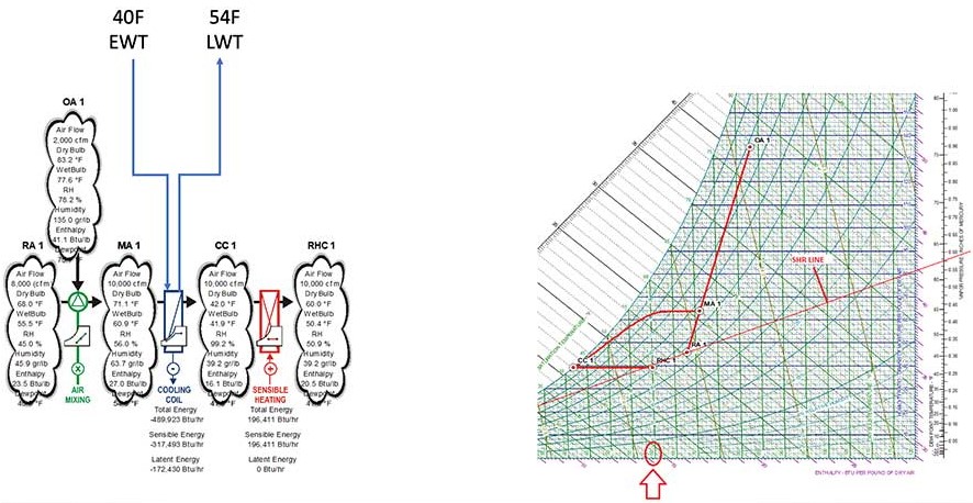
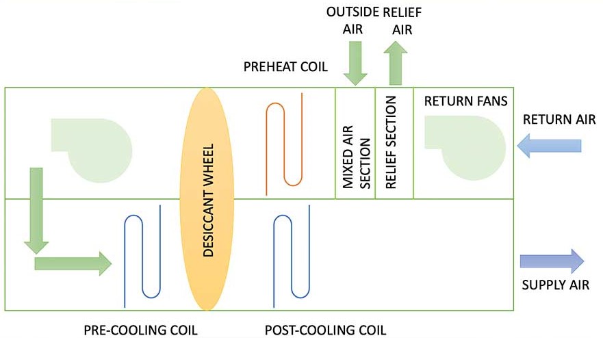
Figure 7 shows a psychrometric analysis of a series dehumidification process that uses a desiccant wheel. As the hot air passes through the desiccant wheel, it gives up heat (which is transferred to the cold airstream) and picks up moisture (transmitted by the cold airstream). The precooling coil is then used to cool the air (typically around 44°-45° DB). The cold but still humid air that leaves the precooling coil is then “dried” when it passes through the other half of the desiccant wheel. As the air passes through the “cold” half of the desiccant wheel, it gives up moisture and also picks up heat. Depending on the design conditions and the type of wheel that is being used, a post-cooling coil could also be needed to cool the “dry” air down to a standard supply air temperature of approximately 55°. It’s important to note the purpose of the post-cooling coil is to provide only sensible cooling; it will not be able to remove any moisture from the airstream.
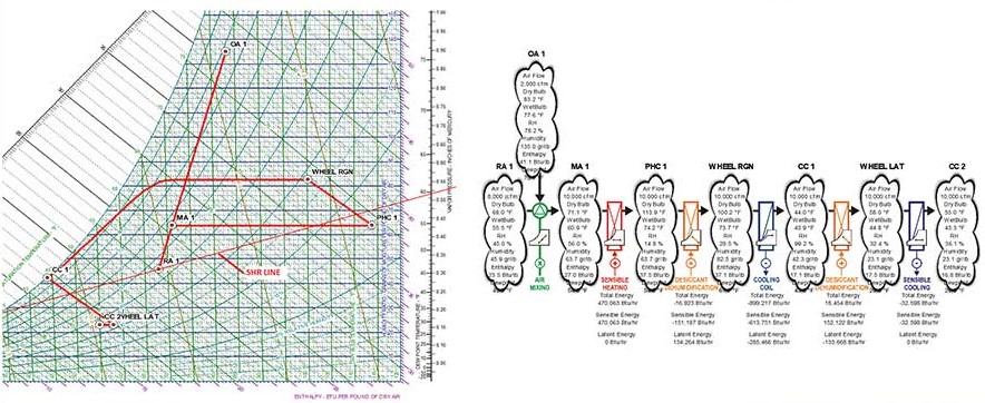
Although desiccant wheels can dehumidify air down to what can be considered very dry air (i.e., 68° and 30% RH), during the summer months, the process of dehumidification uses significant amounts of energy. As shown in Figure 7, and excluding the fan energy required to push the air through the wheel, approximately 470 MBtuh of heat (the heat needed to reactivate the wheel) are needed to remove approximately 130 MBtuh of latent heat, representing almost a ratio of 3:1; that is one has to spend 3 Btu of sensible energy to remove 1 Btu of latent energy. This is one of the main reasons that prevent the desiccant wheels from being used more broadly for dehumidification purposes.


