


Hot water.
Those words spurn up a variety of thoughts and feelings. To some, hot water is the metaphorical comparison of being in trouble. To others, hot water is comforting, as it reminds them of the nice showers they typically start their days with. Engineers designing hot water systems are reminded of two design points: It takes energy to keep water hot for occupants, and bacteria grows in the pipes carrying hot water.
Analyzing hot water return (recirculating) sizing and its importance is the focus of this article. Designing a hot water system is not like designing other building systems. There are shared ideologies, but the approach between a hot water system and other building systems forces one to consider what is best for the owner as it relates to the balance between saving energy and safety. The hot water system consists of three main facets: supplying, heating, and recirculating the water. Codes help size the hot water supply pipe but largely leave out sizing guidelines for the other two facets, leaving it up to the designer. For an entry-level designer, there is minimal information to help. Water heater sizing comes from experience. Typically, the hot water return piping is sized in tandem with the recirculation pump as the next iteration of sizing will give the project a better design.
When sizing a recirculation system, designers must discover who the users are within the building while also considering the type of fixtures connected. They may ask the owners questions, such as: Will the building be occupied by people with a weaker immune system? Are there any showers? Does the local jurisdiction have temperature requirements for this system?
Determining the users and the type of fixtures helps determine the hot water design. Asking the aforementioned questions is paramount to avoid surprises in the middle of a project in a situation where equipment may need to be added to complete the hot water design.
Engineering designers should consider: “Should the design be energy-conscious, or shall we be overly concerned about bacteria growth?”
Sustainability and Energy Consciousness
If the focus is to be more energy conscious, we must first identify the sources of energy usage:
- It takes energy to heat the water;
- Heated water is used by occupants of the building;
- It takes energy to keep water “hot;” and
- It takes energy to pump/recirculate the water throughout the building.
Now that these sources are identified, each can be isolated in an effort to explore how the energy is used and determine if energy use can be minimized.

FIGURE 1: Heat transfer is the process in which energy communicates from a body with higher energy to a body with a lower energy source, more simply, from high to low temperature. Images courtesy of SmithGroup
Heating the Water
Heating water can be done in many ways, and energy usage comes in many forms. There are high-efficiency options for heating water, including condensing boilers, water-to-water heat exchangers, steam, electric resistance, and heat pumps. ASHRAE 90.1 serves as a reference regarding the minimum performance required.
Water Usage By Occupants
Even if heated water would not be used, we need to consider water consumption as a potential source of energy savings.
The designer can create a system to limit the hot water by specifying fixtures with known flow rates. The plumbing code lists maximum flow rates for fixtures like showers and sinks. As such, the designer can select fixtures that use the maximum flow rate, or the designer can opt to specify fixtures with flow rates lower than the maximum. For buildings looking to be LEED-accredited, it’s common for fixtures to be selected using 20%-30% less water. The fixtures using hot water in LEED water calculations include showers, sinks, and lavatories. LEED offers guidance in the duration of each fixture’s use, (e.g., lavatories are used for 30 seconds, a sink is used for 15 seconds, and a shower is used for five minutes). If water usage is throttled by 20%-30% at the fixture, then the energy used to heat the water would be saved at the same 20%-30% rate.
Water usage that is not typically factored in is the water that is used until hot water comes out of the faucet/spout. For lavatories/sinks, it is common to wash hands/dishes with colder-than-desired temperatures. For showers, if hot water is not readily available, it’s common for water to be wasted until hot water comes out of the showerhead. Preventing wasted water would be a large energy saver. If the design was such that there is nearly zero time for the water out of a showerhead to be hot, then the user(s) ideally would not need to wait before entering.
The International Energy Code (2015 and later) now requires recirculating hot water to be within a certain distance from a fixture (see Table 1). For showers, the distance is 25 feet for a ¾-inch pipe. At this distance, and assuming a 2 gallon per minute (gpm) flow rate at the showerhead, it would take more than 15 seconds before hot water is realized at the showerhead. This can be improved. Designing the system to have a maximum distance between recirculating water and shower of approximately 7 feet would achieve a five second reaction time for the shower to see hot water.
Keeping the Water ‘Hot’
Hot water is supplied to showers and sinks through a network of piping. Potable water from the street flows through a water heater and then to a fixture. If the furthest fixture is away from the water heater, then code will require a recirculation system be provided. Per the International Plumbing Code, a fixture exceeding 50 feet from the water heater is the cutoff limit requiring a recirculating pump, which is why so many buildings have this pump. Hot water that is not used at a fixture will circulate back to the water heater before being supplied (again) through the network of piping. This occurs in perpetuity until a fixture is opened and the water flows out the spout.
Heat transfer is defined as the process in which energy communicates from a body with higher energy to a body with a lower energy source, more simply, from high to low temperature.
This means the piping network of supply and circulating water will transfer energy to the building. We know this because a building is typically conditioned to be around 70°-75°F, and the water circulating in a “hot” water system is at a higher temperature. The simplest form of heat transfer is represented by this formula:

In this equation, Q is energy transferred, m is mass, c is the specific heat of the fluid, and T is the temperature difference between two fluids. In this case, the water would be “Thot,” and the air of the building surrounding the pipe would be Tcold. To be energy-conscious would be to have the lowest-resulting “Q” for the design. Let us assume mass cannot be affected/changed, the specific heat, or the temperature of air surrounding the water piping. Assume 75°F is Tcold. This would leave only Thot in the equation not accounted for. Thot is equal to the temperature set point the water heater is set at.
When examining the available range for Thot: On the high-side, water is a liquid until 212°F; and, on the low-side, when the water temperature equals Tcold, there would be zero heat transfer.
This is a wide range of temperatures to consider. Luckily, code offers direction for the designer. In Chapter 5 of the International Plumbing Code (2018), there is an indication/recommendation that 140°F is the maximum water temperature that should be distributed to a building. In Chapter 6, section 607, it is stated that water temperature-limiting devices shall conform to ASSE 1070 and the water shall be limited to 110°F. This may sound like 110°F is the code’s low limit, but if an ASSE 1070 device’s cut sheet is reviewed, it will be found that the minimum water temperature for hot water inlets is 120°F. These ASSE 1070 devices are called thermostatic mixing valves. To further complicate identifying the minimum Thot, the loss of heat as water flows from the water heater to the thermostatic mixing valve must be considered. If 5°F is lost from the water travelling from the water heater to the further mixing valve, a minimum Thot would be 125°F, for instance.
Diving into an example, let us assume a hospital with a hot water supply and recirculating/return piping as shown in Tables 2 and 3.
From these lengths of pipe, how do we determine the amount of energy loss?
We need to first determine the heat loss for each pipe size. There are two ways to go about this. The longer way is to calculate the heat transfer from the hot water to the air surrounding the pipe by using generally known material properties to calculate how many Btu transfer per hour. The shorter way is to ask a few insulation manufacturers to calculate heat loss per linear foot after giving the pipe material type, insulation material, water temperature, and air temperature.
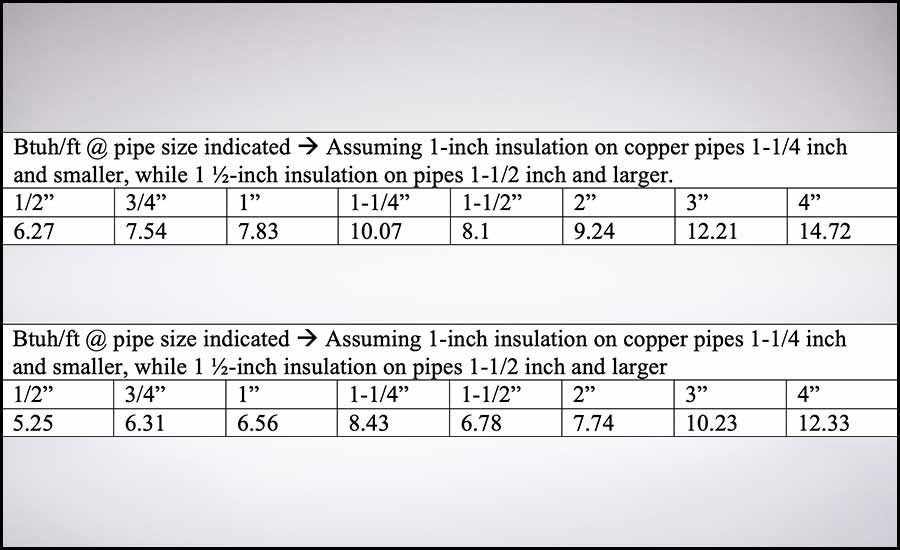
After discussing with insulation manufacturers, the Btuh/ft loss for insulated copper pipe carrying 140°F water in a 75°F plenum at the associated pipe sizes is shown in Table 4.
We ultimately find the supply system piping loses 23,655 Btuh and the return piping loses 15,574 Btuh for a total of 39,230 Btuh.
If 140°F is Thot for the above calculation, let’s use 130°F for Thot in another calculation. From the manufacturers, the Btuh/ft loss for insulated copper pipe carrying 130°F water in a 75°F plenum at the associated pipe sizes is shown in Table 5.
Through this calculation, the system losses total 32,846 Btuh. By setting the water heater 10°F lower, 6,384 Btuh, about 16.3% of energy can be saved from these standby losses.
What does this mean? Assume the pump circulates water 24/7/365 in a hospital. Also assume the water heater is natural gas input, and, because of a high return water temperature, the condensing boiler is 85% efficient. Assuming the cost of 1.0 Therm from the natural gas company is $1, the equation looks like this:
(39,230 Btuh – 32,846Btuh) * (24 hrs/day) * (365 days/year) * (efficiency/85%) (1Therm/100,000 Btu) * ($1/1Therm)
In this example, the hospital would save approximately $658 a year if the water temperature distributed from the water heater was 10°F lower.
Editor’s Note: The temperature set points, water heater efficiency, and utility costs were assumed for the calculation. Consult local codes and jurisdictions on a project basis.
Pumping Water throughout the Building
In the example from the previous section, heat loss by the recirculating portion of a hot water supply system was calculated. During the example, it was assumed the temperature of water was uniform. We know this is false, as there will be heat energy loss as the water flows further away from the heating source.
How much does the temperature reduce?
Temperature reduction is largely up to the designer and the flow produced by the recirculation pump. We must use a formula to observe the relationship between flow and temperature in the system.

Where Q is flow (gpm), q is the heat loss in the recirculating piping system (Btuh), and ΔT is the maximum allowable temperature drop throughout the system, Thot and Treturn.
If we continue with the example from the previous section using 130°F as Thot, then we can input values for q and the starting temperature, but the flow and ending temperature are unknowns. Entering in flow values to determine the resulting temperature is one way to approach the problem, and this makes sense if an existing system has a recirculation pump and the temperature resulting was being calculated. In new construction, the resulting temperature, Treturn, is the value that is manipulated to determine flow that is needed by the recirculation pump. It is up to the designer to consider what is more important in the design, safety, or energy usage. If safety is the most important factor, a higher starting temperature might be a good idea (see below for more information on safe temperatures), but if energy is the important decider, then keep the hot water temperature in the supply side above the limit required for an ASSE device to work, which is approximately 120°F.
Q is unknown and the flow we are solving for.
qsupply is equal to the heat loss on the supply side, 19,808 Btuh;
Thot is 130°F;
Treturn is 120°F; and
ΔT is 10°F.
Q = (19,808) / (500 * 10) = 3.96 GPM = ~4 GPM
It would be up to the designer to then select a pump that can provide ~4 gpm to the system. One caveat is that most balancing valves have a minimum flow rate required. Historically, this minimum flow is ~0.5 gpm. In the example used, the measurement lengths came from a previous project, where 26 balancing valves were used. Using the historically used balancing valves would require the system’s pump to provide a minimum of 13 gpm (26 * 0.5 gpm). Assuming a 13-gpm pump is selected (and qsupply at 19,808), the resulting temperature for the supply water would be 127°F.
If the return piping was included using the 13-GPM pump, qtotal would be 32,846 Btuh, then the resulting temperature would be 125°F.
Potential energy savings does not end there.
There are many types of pumps and balancing valves, and designs can be optimized with more sophistication. Notably, the 4 gpm calculated was assuming no occupants were using hot water, and that the pump would operate at 100% capacity. It is safe to assume water would not be used every second of every day, but occupied buildings will have users that will wash their hands, take showers, and clean. Use of hot water keeps the supply temperatures elevated and lessens the need for the recirculation pump to operate at 100%. To be energy-conscious, the designer can specify sophisticated balancing valves and pumps to take advantage when occupants use water.
What options are available? Tables 6 and 7 offer a few pump and balancing valve options.
Historically, a constant volume pump on a time clock would be used with ball valve-type balancing valves. It could be cost that is the driver continuing to include these products in projects today. This approach does not offer turn-down of the pump when occupants are using hot water.
Multi-turn balancing valves offer better control on the limiting flow through a balancing valve where a Cv less than 0.5 is desired; however, if a pump throttles down/off, then the further-away fixtures (in relation to water heater) likely would not see as much recirculation as the balancing valves nearer.
Thermostatic balancing valves offers a benefit of throttling to a full-open position and to a mostly closed position based on the temperature of recirculating water, allowing the benefit of hot water recirculating prioritization. This means that if there are users actively showering/washing on one level, the recirculation on that level would reduce while the other levels of a building would have increased recirculation.
An aquastat is a probe that is installed on the water pipe upstream of the recirculation pump that notifies a building management system (BMS) of the temperature measured. The BMS can be programmed to interpret this temperature and command pumps to do any number of things. For a constant volume pump, when a temperature (of say 125°F) is reached, the pump can be commanded off for 10 minutes before being re-energized. For electronically commutated motors (ECMs) and variable frequency drive (VFD) motors, the BMS can command the pumps to vary in speed output to reduce the flow because occupants are using water, and thus a higher-than-designed water temperature is returned after being distributed and returned to the water heater.
VFDs offer turndown safely to ~20Hz to give a 3:1 turndown ratio.
In the example above, a 5°F temperature drop was selected for the entire system, and the resulting pump moved 13 gpm. This pump had a 0.5-hp motor, which is ~373 W. The building was a hospital, so it is required to run 24 hours a day for safety. If the pump was constant volume, it would use ~3,200 kWh/yr., and with $0.12 per kWh, the cost would be just shy of $400 a year.
In the same example, if a VFD was provided, and, on average, the pump ran at 50% speed, then by use of the pump affinity laws:
Phalf / P100% = (Speedhalf / Speed100%)3
The total power used would be 12.5%, saving ~$350 a year, but the water would be kept hot throughout the entire system at periods of no flow.
Safety in Hot Water Design
Two considerations on introducing safety in the design include the water temperature not being hot enough, and the water temperature being too hot.
In the world of water, the amount of bacteria, biofilm, and subsequent pathogen growth in piping networks tends to scare people. For the most part, it goes unnoticed due to the relatively low percent of proper diagnosis of waterborne diseases, such as Legionnaires, and healthy individuals being able to stave off serious side effects. Legionnaires is especially dangerous when introduced to people with weakened immune systems as well as the sick and elderly. The bacteria legionella thrives in water temperatures between 68°F and 122°F but is killed in temperatures 132°F and greater. Bacteria grows in stagnant water; caution in equipment selection and pipe routing must be used because the portions of the system between recirculating water and the fixture are stagnant for periods of time, and even if the recirculating portion of system is at an elevated temperature, natural-forming biofilm will provide an insulated barrier for bacteria to grow and multiply.
Hot water circulating can curb bacteria growth, and it is important to maintain high hot water temperature (supply and return) throughout the entire system while also minimizing any dead legs. Between a recirculation pump system; efficient sizing of mains, branches, and drops; a master mixing station for the supply side of the domestic heating plant; point of use mixing valves and balancing valves; and a properly maintained complete domestic hot water system (supply and return) can do an excellent job of bacteria prevention and mitigation, but not on its own. There are many layers to consider approaching this design, including water entrance filtration, general system chemical treatment, and systems such as copper silver ionization that must be explored with the project team and/or owner.
There is a significant amount of effort that can go into a complete domestic system when it comes to minimizing bacteria. As with most things in life, there are checks and balances that create the impossibility of a perfect system. Legionnaires’ disease is contracted from legionella, and the primary mode of infection is from aerosolizing water out of showers or non-laminar flow faucets. One could argue that eliminating any aerosolized water in a facility could be considered part of a safety plan, but that leads to the ever-present question of ethics that can always be brought up in design.
The other safety consideration to account for is water being too hot. Often in hot water design, water is heated to temperatures greater than 140°F as a way to prevent legionella growth. By code, there should be both a master mixing valve limiting the maximum distribution temperature to 140°F and point-of-use, ASSE-listed, anti-scalding devices at fixtures like lavatories and showers; however, 140°F can scald a person in three seconds, 130°F scalds in ~20 seconds, and 158.3°F scalds instantaneously. Designs and installations should have the hot water return piping connected per water heater manufacturer recommendations; complex water heater systems require one connection upstream of the water heater and a second connection downstream of the water heater and upstream of the ASSE 1017 master mixing valve.
Existing buildings that get renovated need particular attention to scalding prevention. Anti-scalding devices were not widely adopted to be required by local building codes until the 1990s and 2000s. Existing buildings built prior to this time likely are missing local anti-scalding protection. The owner should be made aware of these issues as early in the project as possible to avoid scalding users on showers/lavatories that were not intended to be affected by the renovation.
What Does it All Mean?
As a designer, user, or owner, it is important to know your building's hot water system. The project team must decide if it will seek to save energy or value the health of the occupants. If there are not any showers, and it is an office building, energy savings is probably the design-factor in the hot water design. If the building has showers and is a setting where occupants have a weakened immune system, designing with safety in mind would be a great idea for a resilient approach. Safety is a worry when water is too hot and not hot enough, so when the owner wants a completely safe system, exploring the introduction of a filter, chemical, and/or ion exchange system would be a worthwhile exercise to design a system that can achieve greater energy efficiency and safety to the occupants.


