The 2015 International Mechanical (IMC) and Building (IBC) Codes provided new and clear guidance for ceiling radiation dampers (CRDs) that affect architects, engineers, specifiers, contractors, and building inspectors. If not recognized and addressed from the beginning of a project, these code revisions could result in confusion, design changes, delays, and costly rework for project managers and other stakeholders.
Since the early part of the 20th century, ceiling designs tested by third-party testing agencies, such as Underwriters Laboratories (UL), have been performed in static airflow conditions. Static air flow condition means that the ceiling (with one or more ceiling dampers installed) is exposed to a controlled fire, however no air movement through the ceiling damper(s) is ever imposed. The test standard for which ceiling radiation dampers are tested and classified to is UL555C. The controlled fire exposure is based upon UL263 (ASTM E119).
Ceiling radiation dampers serve a critical safety element, where HVAC ducting penetrates a fire-rated ceiling. When elevated temperatures are detected by a ceiling radiation damper, the damper activates to close off the area of the open ceiling (typically located above a supply air register) and in doing so maintains the fire-rated integrity of the ceiling. Naturally, ceiling radiation dampers are typically subjected to airflow movement, which is considered a dynamic condition, not static. Yet as noted earlier, testing and certification for these ceiling dampers has been in all cases under a static condition.
For decades, UL engineers have discussed this disconnect of test lab results versus real-world conditions with engineers of damper manufacturers. One interesting point is that unlike ceiling radiation dampers, Fire dampers, which are normally of a metallic curtain design, are tested and classified as “static” or “dynamic” depending on how the damper is tested. Fire damper designs normally provide a means to keep a damper closed during heated airflow tests at specified air velocities. Both types of fire dampers are available on the market today. Optional control switches that can detect when a fire damper closes so that a signal can be provided to an air handler are also available to the system designer.
Because of this disconnect between lab testing methods and real-world conditions that result in an air handler continuing to operate while a ceiling damper has activated due to the event of a fire, UL made a significant change to UL555C in January 2011. New language was added to evaluate ceiling radiation dampers for dynamic fire exposures. As a result of this change, manufacturers were required by UL to indicate on each UL label whether the ceiling damper marked was “static” or “dynamic.”
During the next cycle change, the International Code Council (ICC) approved language in the IMC and IBC that reflected the changes UL published in UL555C regarding ceiling dampers approved for “static’ or dynamic applications. In short, the IMC and IBC revision required that only dynamic ceiling radiation dampers be allowed for applications when air movement is not deactivated at the start of a fire. This was a watershed change. As the 2015 national codes become adopted by jurisdictions in the years after the 2015 IMC and IBC publication, awareness of the need for dynamic solutions to ceiling damper applications will be, and already has been in some regions, greatly amplified.
Specific code language to be aware of per the 2015 ICC publications include:
2015 IMC – Section 607.3.1 was revised to specify that “Only fire dampers and ceiling radiation dampers labeled for use in dynamic systems shall be installed in HVAC systems designed to operate with fans on during a fire.”
2015 IBC – Section 717.3.1 was revised to specify that “Only fire dampers and ceiling radiation dampers labeled for use in dynamic systems shall be installed in HVAC systems designed to operate with fans on during a fire.”
Furthermore, changes proposed to the 2021 IBC and IMC have been generally accepted to clarify “other options” to that of a dynamic CRD due to the lack of such a product being available to the market. Solutions such as smoke detection, control switching means (similar to what is currently offered on fire dampers), and other sensing mechanisms that can be wired electrically from each ceiling damper to control a dedicated air handler (i.e. forced-air furnace) are solutions that can meet the most recent national code requirements. However, these options require skilled labor, additional components, and design allowances that result in higher installation costs compared to earlier times when local jurisdictions simply allowed a static ceiling damper to meet code requirements.
Why Dynamic Ceiling Radiation Dampers Are Special
What makes a dynamic ceiling register damper unique from the typical UL555C dampers currently available on the market is the ability to protect a ceiling membrane from total collapse while air is being pulled or forced through the ceiling. One can imagine the excessive heat above a ceiling membrane that results from pulling air out of a full-scale test furnace that is generating temperatures in excess of 1,700⁰F. The heat radiating from the damper/plenum box and ducting located between the ceiling and floor assembly can be quite severe when compared to a static condition.
Likewise, for cooler air temperatures that are forced into a room engulfed in flame, a new source of oxygen to fuel the fire under a dynamic condition raises further concerns that cannot be simply swept away without thorough investigation provided by the UL555C damper test standard. Another concern would be whether the ceiling damper activates immediately (say within the first minute of a fire) or remains open for the duration of the test. Cooler air forced across the damper will most certainly change the typical closure time of a damper when compared to the traditional static pressure tests performed in past decades. UL was justified in revising the UL555C standard so that fire-resistance-rated floor/ceiling design could be investigated for such a condition if provisions to turn off an air handler are not part of the building design.
The UL555C test standard provides the tools and guidance to investigate ceiling damper designs to ensure that a solution to both conditions noted above are tested and evaluated. Such testing provides assurances to the manufacturer, building owner, inspectors, engineers, contractors, and architects that the minimum safety requirements specified by national building and mechanical codes are maintained.
Summarization
Effective when jurisdictions adopt the 2015 (or newer) IMC and IBC, where “static” labeled ceiling radiation dampers are installed in a fire-rated floor/ceiling, means to turn off air-handling equipment at the start of a fire are required.
This can be accomplished with costly electrical control systems that are possibly unique to each building design. The simpler solution to the problem is solved by using “dynamic” ceiling dampers that are listed and labeled for such conditions.
The concept is not new to the industry where listed dynamic fire dampers are utilized, however there will be a learning curve for the industry to understand and embrace this new development in code changes for ceiling radiation damper applications. Failure to understand these changes can result in red-tagged situations from building inspectors and costly corrective measures to meet the new requirements.
Test Standard Requirements for Dynamic Ceiling Radiation Dampers
UL555C Safety Standard for Ceiling Dampers is a collection of tests that thoroughly evaluate a celling damper design. Testing includes extensive cycle testing, corrosion testing, and evaluation of spring force that exceeds actual force required for blade closure. Full-scale fire tests exposures to ceiling designs that a damper can be classified for is a requirement that includes a large ceiling that is dead loaded before exposure to a time-rated fire exposure per UL263 (ASTM E-119). Such fire exposure tests are costly endeavors and for some ceiling structures (such as solid wood joist and open wood truss construction) very near failure points even without the addition of a “dynamic” system exposure.
For Dynamic CRD testing and classification, a ceiling damper design must comply with 2 full-scale tests. One that proves that the ceiling damper (and ceiling) can withstand an hourly exposure while the minimum rated air velocity (determined by open area of the damper at the ceiling membrane) is flowing as a “return air” to the air handler and a second full-scale test that reverses the air flow to be a “supply air” condition originating from the air handler.
In addition, the UL test standard requires that a Dynamic CRD pass AMCA 500-D for a dynamic closure test.
This test applies forced air flow at an air velocity that is 20% above rated velocity and gradually elevates the ducted air temperature until the ceiling damper activates (closes). Static pressure drop across the closed damper is measured to establish a minimum pressure of 1.13 inch w.c. As similar to Dynamic Fire Dampers, a ceiling damper will likely include a latching means to maintain closure once a damper activates, and this test confirms that the latching design works as intended as the damper closes during air flow at an elevated temperature.
Upon completion of all UL555C tests for dampers that are evaluated as part of a UL fire-resistance-rated floor-ceiling, the damper model then becomes part of the floor-ceiling design and can be traced back to the testing agency’s design listing directory.
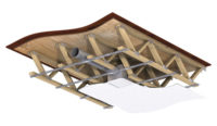
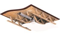
At the time of this article’s publication, there has only been one ceiling design established that includes listed dynamic ceiling dampers (UL Floor/Ceiling Design No. M557).
The ceiling design depicts two dynamic ceiling damper models that meet the minimum requirements of UL555C for dynamic ceiling radiation dampers. The floor/ceiling design includes an open-wood truss construction similar to numerous floor/ceil-
Words of Advice
Architects and engineers: For fire-rated floor/ceiling designs that require ceiling radiation dampers, be aware that national codes require a solution to shut off air-handling equipment in the event of a fire in any room that equipment serves.
Demand that only ceiling dampers that are listed/labeled dynamic be used (as required by code) or provide a system design to ensure that air-handling equipment is shutdown at the start of a fire.
Specifiers: Include new code requirements for ceiling dampers that are labeled for dynamic conditions where applicable.
If such a solution is not possible, provide specifications for options that are acceptable to ensure air handling equipment will shut down at the start of a fire.
Contractors: Know your codes and requirements in the area having jurisdiction. As the 2015 national codes are adopted in regions of the U.S., the option of using a typical ceiling damper that is marked static will no longer be acceptable unless other means are provided to turn off air-handling equipment at the start of a fire within a room the air handler services. Understand the cost for providing other means to shut air handling equipment off during a fire. Press your supply chain for dynamic ceiling radiation damper products that omit the need for costly optional means now required by national codes. Finding the least costly solution to the new code requirements for dynamic ceiling dampers will result in greater success and less headaches for your business while also providing the best safety for your customers.


