


The topic of motors and motor control techniques is wide and varied. Part one of this two-part article will cover the principles of alternating-current (AC) motor operation and control. Part two will cover design considerations for AC motors with variable speed drives and electronically communicated variable-speed direct-current (DC) motors (ECMs), followed by a comparison table of suggested advantages and disadvantages and design considerations for each type, and concluded with a case study comparing the use of AC motors with variable speed drives (VSDs) with ECMs.
The most common type of motor used in HVAC fan and pump applications is the three-phase AC induction motor (IM). DC motors also have applications in the building and HVAC systems — in particular, many elevator designs employ DC motors. Compared to DC motors, AC motors are simpler in design, are more rugged, and have a longer life under normal operating conditions.
BASIC PRINCIPLES OF MOTOR OPERATION
The Lorentz Force Law relates the direction and speed of the rotor windings as they pass through the stator magnetic field to the force applied at the circumference of the rotor and to the resulting torque.
When a charged particle, q, is placed in a magnetic or an electric field, it is acted upon by a force. This is analogous to a force acting on a mass placed in a gravitational field(1).
The Lorentz Force Law describes the combination of forces on a charged particle when placed in an area that contains both an electric field and a magnetic field.
Lorentz Force Equation: F ⃗=qE ⃗+qv ⃗ X B ⃗ [Eq 1]
Two forces are present in this equation:
The force due to the electric field, F ⃗=qE ⃗ [Eq 1a]
The force due to the magnetic field, F ⃗=qv ⃗ X B ⃗ [Eq 1b]
As indicated in equation 1, the variables are vector quantities, while is a scalar quantity. The values are defined as follows:
B ⃗ , Magnetic field strength T, Wb/m2
E ⃗ , Electric field strength V/m, N/C
F ⃗, Force (N)
q, charged particle (C)
v ⃗ , velocity of charged particle (m/s)
For this discussion we will put aside the force contribution from an electric field and concentrate on the force resulting from a magnetic field. One difference between the effect of an electric field and the effect of a magnetic field on a charged particle is that while an electric field acts on a charged particle at rest, a magnetic field acts on a charged particle in motion and motion of a charged particle in a magnetic field is the nucleus of motor rotation. Referring to equation 1b we note that the magnetic force, F, is the result of the cross-product between a charged particle in motion, qv, and the magnetic field strength, B, where F, v, and B are all vectors. A magnetic field can be visualized by lines of magnetic force originating on the north pole of the field and terminating on a south pole where the line density per area represents the strength of the field. A charged particle moving through this field will move in one of three ways relative to the field lines: parallel, perpendicular, or skew. The magnitude of the force acting on the moving charged particle is summarized below:
- Parallel motion: no force;
- Perpendicular motion: maximum force; and
- Skew motion: force less than maximum, depend on angle between field line and particle direction.
The above bullet points can be described mathematically by the fact that the cross-product of two vectors results in a third vector that is perpendicular to the first two vectors and whose magnitude equals the product of the first two vector magnitudes multiplied by the sine of the angle between the first two vectors. In our case, the magnitude of F ⃗ is
F =q|v ⃗ ||B ⃗ | sin(θ), , where θ equals the angle between v ⃗ and B ⃗..
In the principles of induction motor operation, the charged particle, q, in motion, v, represents current flow in the rotor windings and the magnetic field, B ⃗., represents the magnetic field setup by the magnetized poles of the stator.
Another form of the equation is:
F=BIL sin(θ), [Eq 2]
In this form of the equation, B, again, represents the strength of the stator magnetic field, I represents the current flowing in the rotor windings, L represents the length of the windings, and represents the continuously, varying angle formed between the direction of the stator magnetic field and the direction of the alternating current flowing in the rotor as it moves through the stator magnetic field. The resulting force acts in a direction perpendicular to both the stator magnetic field and the direction of current flow in the stator windings. This force, acting at a fixed distance from the rotor center-line, produces a torque about the rotor, causing it to rotate.
Torque
When a force is applied about an axis (referred to as the axis of rotation) at a fixed distance, such as tightening a nut with a wrench, this force is referred to as torque.
Torque equation: τ=rFsin(θ),, where θ represent the angle formed between the direction of the force and the line falling along the radius. In the wrench example above, the radius represents the length from the center of the nut to the end of the wrench where the force, F, is applied.
In the operation of a motor, the applied force, F, is determined from equation 2 above, (reprinted here for reference) and the radius corresponds approximately to the radius of the rotor.
Torque, as applied to induction motors, can be defined as a force acting at a distance r (rotor radius) where the axis of rotation corresponds to the rotor axis. Torque is measured in Newton-meters (Nm).
The Torque output of an induction motor is related to and dependent upon the value of slip as shown in the following equation:
(ksE_2^2 R_2)/(R_2^2+ (sX_2 )^2 )
Where:
E2 = induced rotor voltage
R2 = resistance of rotor windings
X2 = reactance of rotor magnetic field
S = slip where s=(%s)/(100%) ,(0≤s ≤1)
k= 3/(2πN_s^' ) and N_s^'= N_s/60
From the above torque equation, it can be shown that:
- Torque is proportional to the current flowing through the rotor windings, (τ ∝ i);
- The angular velocity of the rotor is proportional to the voltage across it (ω ∝ E); and
- At synchronous speed (s=0) torque is zero.
Power
Recall the following from physics:
- Work is defined as a force applied through or along a distance and is measured in Newton-meters (Nm) or joules (j).
- When the force is applied at a distance about an axis of revolution, the work is referred to as torque. The unit of torque is also the Nm.
- Power is defined as work per unit time and is measured in Newton-meters per second (Nm/s). Nm/s or J/s also known as a watt (W).
- Another measure of power is the horsepower and is equal to approximately 745.7 Watts
Motor Speed
The rotational speed of the stator magnetic field is determined by two components.
- The electrical frequency of the AC line current flowing in the stator windings.
- The number of magnetic poles (or pairs of poles) located in the stator.
As described above, the AC current flowing in the windings of the motor’s stator generates a rotating magnetic field. The stator field rotates with a speed that is directly proportional to and is in time-phase with the electrical frequency of the AC line current and is, therefore, referred to as synchronous speed. The synchronous speed is determined by the frequency of the electrical line current flowing in the stator windings and the quantity of poles in the stator.
Synchronous speed, n_s= 120f/p
or, less commonly n_s= 60f/pp
Where:
f = the frequency of the electrical line current in Hertz (Hz) or cycles per second
p = number of poles. (Always occurs in multiples of 2). In a multi-phase motor, p refers to the number of poles per phase
pp = number of pole pairs.
Synchronous speed is measured in rotations per minute (RPM)
The equation shows that synchronous speed is proportional to the electrical frequency, f, and is inversely proportional to the number of poles, p.
Examples:
A 2-pole, 60Hz motor rotates at
120 * 60 / 2 = 3600 RPM
A 4-pole, 60Hz motor rotates at 1
20 * 60 / 4 = 1800 RPM
AC INDUCTION MOTORS AND VARIABLE-SPEED CONTROL
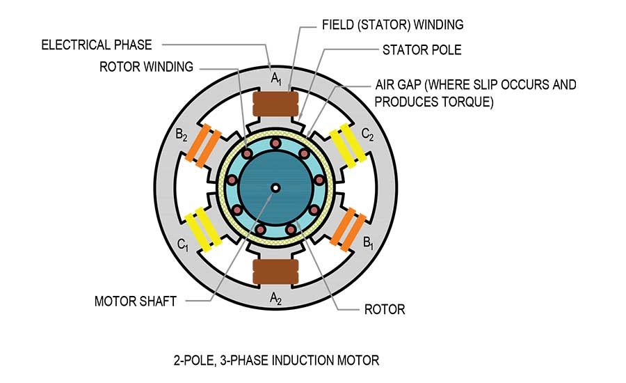
An AC induction motor is comprised of an outer, fixed structure called a stator. The interior of the stator is comprised of metallic poles, and an axial motor shaft that supports and is connected to a solid metal cylinder called a rotor. The end of the motor shaft is connected to the load, such as a fan. AC motors are designed with an even number of poles per electrical supply phase (2-pole, 4-pole, 6-pole, etc.). They are manufactured to run on either a three-phase power supply or a single-phase power supply. A 2-pole, single-phase motor will have only two poles in the stator – a north pole and a south pole. A 2-pole, three-phase motor will have six poles in the stator – a north pole/south pole pair for each of the three electrical supply phases.
In image 1, conductive wiring is wrapped around one of the slots a fixed number of times (e.g. clockwise) and then continues on to wrap around the opposing slot in the opposite direction (e.g. counterclockwise). Instead of wire, conducting metal bars may be used. The wiring or rod laid in the slots is known as a winding. The windings are connected in a manner that allows a pair (2) of opposite polarity magnetic poles to be established. One end of the winding is connected to an external AC circuit (phase conductor) and the other end of the winding is connected to the neutral point in a wye-connected 3-phase motor or to an opposite-polarity pole of an adjacent phase. When AC current flows in the windings of the poles a magnetic field is established between the north and south poles of each pole pair. The magnitude (strength) of the magnetic field is directly proportional to the value of current flowing in the windings — when the current in phase A reaches a maximum, the associated magnetic field reaches a maximum.
Each of the three AC phases (A, B, and C) is 120 electrical degrees out of phase (time-shift) with the other two phases. This spacing of 120 degrees allows for only one phase at a given instant to be at its maximum positive value (north pole). The operation of the AC induction motor is based upon principles of electromagnetic laws, including Faraday’s Law of Induction, Ampere’s Law, and the Lorentz Force Law. In an AC motor, two rotating electromagnetic fields are formed that result in the rotation of the rotor. AC line current flowing in the windings of the IM’s stator establishes a rotating, time-varying, magnetic field within the interior of the IM. The time-varying nature of the stator magnetic field (specifically, the portion of the field located in the air-gap between the face of the stator poles and the face rotor) interacts with the windings of the rotor to induce a magnetic field within the moveable rotor. Rotor motion occurs when the magnetic field around each rotor winding (initially stationary) acts to align its magnetic north pole with the nearest magnetic south pole of the stator’s rotating field. The same is true for south poles in the rotor field act to align themselves with the north poles of the stator field. The effects of electromagnetic interaction cause the rotor field to rotate at a slower speed than the stator field. The difference in speed between the two fields is referred to as the slip speed (or slip). The slip determines the magnitude of the rotational force acting on the axial line of the rotor. This rotational force is known as torque. If the slip (speed) falls to zero, there is no torque acting on the rotor and the rotor will slow down eventually coming to rest.
The difference between the mechanical speed of the rotor and the synchronous speed of the stator magnetic field is referred to as slip and is typically indicated as a percentage of the synchronous speed.
N_s=((N_s-N))/N_s x 100%
Variable Speed Controllers for Induction Motors
There are four primary types of variable-speed motor control methods used to control induction motors operated by a VFD. The first two methods are classified as a scalar control method, and the last two are classified as field-oriented control also known as vector control.
- Scalar Control
- - V/f (volts per frequency or volts per hertz); and
- - V/f with encoder.
- Vector Control (field-oriented control)
- - Open Loop (sensorless) method; and
- - Closed Loop method.
The main difference between these control methods is the algorithm used to calculate the voltage required by the motor at any given moment.
The control methods listed above utilize either an ‘open-loop’ control system or ‘closed-loop’ control system. In an open-loop system, a parameter is set, and the fan will operate at that speed regardless of changes in conditions such as static pressure. In a closed-loop (‘feedback’) system, a sensor monitors output conditions and feeds a signal back to the controller indicating adjustments required to meet the current load conditions. For instance, if the static pressure in a duct changes, a feedback signal will tell the controller the adjustments necessary to meet the new static pressure.
Scalar Controlled VSD
The most common of the above control methods is the V/f method. The V/f method is also the only control method that allows for multiple motor control by a single VSD. Multiple motor control means all motors connected to the same VFD will be controlled in unison. They will start and stop at the same time and all will follow the same speed signal.
V/F represents a ratio fixed by a motor’s rated voltage and rated frequency. For a motor rated at 460 volts, 60 Hertz, the ratio is 460V/60Hz ≈ 7.67 V/Hz.
V/F control is an induction motor control method that maintains a constant V/f ratio. V/F control uses a voltage-controlled oscillator to adjust the VFD output voltage and frequency signal to adjust motor speed (rotor RPM) while maintaining the motor rated V/f ratio. Maintaining this ratio as the voltage varies allows for a constant motor flux to prevent a weakening or a saturation of the magnetic field. If, for instance, the voltage remains fixed and only the frequency is reduced, then saturation of the magnetic field occurs, resulting in potential motor damage.
A VSD using the V/f method is an open-loop system. A VSD using the V/f method with an encoder is a closed-loop system.
Vector (Field-Oriented) Controlled VSD
The process of vector control, also referred to as field-oriented control, (FOC) allows an AC motor to be controlled like a DC motor. This control method applies one or both transforms — the Clarke Transform(3) and the Park Transform(4) — to transform the stator 3-phase current in a stationary refence frame to a 2-phase current-in a rotating reference frame. The 2-phase current is resolved into the two components comprising stator current:
- a flux or magnetizing current component (Id); and
- a torque-producing current component (Iq).
The Clark Transform is used for induction motor control while both the Clark and Park Transforms are used successively for control of synchronous AC motors. Synchronous AC motors are not discussed in this article
Vector control allows for independent control of both components of the stator current (the magnetizing current and the torque-producing current). A VSD using vector control can control torque as well as speed.
Vector control is used to achieve independent control of motor speed and motor torque, similar to how a DC motor is controlled.
With knowledge of the principles of AC motor operation and control in hand, stay tuned for part two of this article. Part two will cover design considerations for AC motors with VSDs and electronically communicated variable-speed DC motors, followed by a comparison table of suggested advantages and disadvantages and design considerations for each type, and concluded with a case study comparing the use of AC motors with VSDs, with ECMs.
Footnotes
(1) Equivalence of force equations for a gravitational field and an electric field:
Gravitational field:
Electric field:

(2) A magnetic pole cannot exist independently and must always be paired with another magnetic pole of opposite polarity. [Gauss’ Law for Magnetism]. A magnetic field always flows from the ‘north’ pole to the complimentary ‘south’ pole. The number of poles is always a multiple of 2.
(3) Clarke Transform - converts the time domain components of a three-phase system (in abc frame) to two components in an orthogonal stationary frame
(4) Park Transform - converts the two components in the frame to an orthogonal rotating reference frame (dq0)
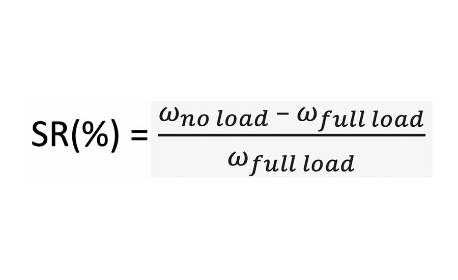
(5) Speed regulation:
(6) IGBT. Insulated Gate Bipolar Transistor. A solid-state switch combing the high-speed switching ability of Field-effect transistor and the high-power rating of a bipolar transistor.


