
In April of 2011, the University of Utah broke ground on a renovation to consolidate multiple production centers into a central multi-tier data center in support of their diverse program mix, which includes the university’s Center for High-Performance Computing (CHPC). Like many institutions, these production centers had expanded over the years but had limited room for growth and did not always have the critical infrastructure needed to ensure reliable operation. These limited spaces also forced mechanical systems to work harder, and, in the process, use more energy.
The renovation, originally the Swire Coca-Cola bottling plant, was built in 1938. The facility’s solid construction helps protect it against earthquakes, and the large site area supports the mechanical and electrical infrastructure needed to serve the data center. Located in downtown Salt Lake City, the site has good proximity to the campus and site utilities. The design goals for the data center included:
- Minimum U.S. Green Building Council (USGBC) Leadership in Energy and Environmental Design (LEED) Silver certification;
- Energy-efficient operation, low power usage effectiveness (PUE);
- Concurrently maintainable (N+1), no single points of failure;
- Flexible infrastructure to support a variety of programs and technology solutions; and
- Systems that are readily available and easy to maintain.
The data center has an installed IT equipment demand of 2.4 MW that, on average, operates closer to 1 MW and can expand up to 10 MW in the future. While the university’s IT equipment is air-cooled, administrators wanted the mechanical systems to be “generically flexible” in support of a variety of cooling strategies. The use of overhead electrical busways also enabled the facility to support varying load profiles and voltages. This combination allows the university to pursue a variety of research grants and colocation opportunities that previously were not available to them.
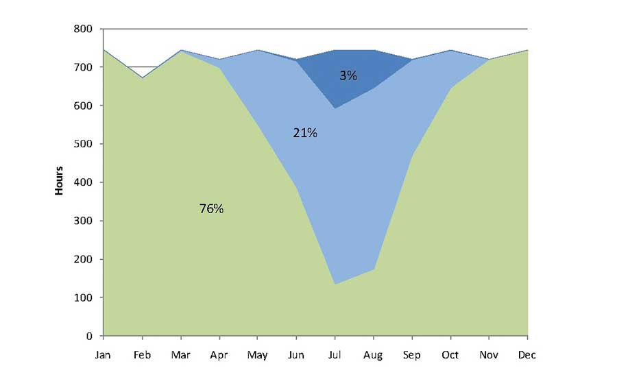
FIGURE 1. Distribution of mechanical cooling operating modes over the year as:
- Green: Outside air free cooling economizer with direct evaporative cooling.
- Light blue: Outside air free cooling economizer with fluid cooler operation.
- Dark blue: Minimum outside air with fluid cooler and chiller operation.
A large portion of LEED certification is related to energy efficiency. For data centers, the PUE is a ratio of the total data center power divided by the IT equipment power. In the 1990s, it was not uncommon for data centers to have PUEs on the order of 2.0 using as much energy to cool and support the building as it did to run the IT equipment. The expanded use of hot aisle containment in the early 2000s isolated hot server air from cold supply air, allowing the temperature of the cooling air supplied to the data center to increase from 55ºF to 72ºF and lowering the average PUE for new facilities to around 1.5 by the time this project was constructed.
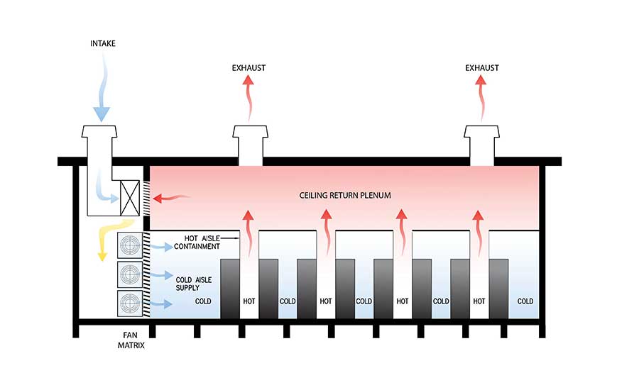
FIGURE 2. The data center mechanical systems’ configuration with the mechanical gallery and AHUs (left), IT equipment racks with hot aisle containment in the IT space (right), and relief fans on the roof above the IT space to relieve hot air.
Unlike most buildings, data centers require cooling year-round. Located in a high desert near the Rocky Mountains, Salt Lake City is a predominantly heating environment with generally dry conditions. Together with hot aisle containment solutions, the mechanical systems in Salt Lake City and similar climates have tremendous potential for free or reduced energy outside air economizer operation. Given that the day-one program was entirely air-cooled, early selections of the systems centered around the use of central AHUs with a focus on the climate.
Most data centers maintain a minimum level of relative humidity to limit the potential to generate static electricity. With hot, generally dry summer outdoor conditions, the direct evaporation of water can also be used to cool the air while adding humidity to the space. Even in the winter months, the ample supply of hot air from the IT equipment allows this same mechanism to maintain relative humidity levels. This combination of outside air economizer and direct evaporative cooling can meet all the cooling needs of the IT equipment for nearly 80% of the year.
For the next 20% of the year, the central AHUs continue the use of outside air economizers and direct evaporative cooling but then supplement with chilled water from closed-circuit fluid coolers. Closed-circuit fluid coolers evaporate water outside of an isolated coil to cool (chilled water) that is then circulated to the AHUs. The remaining 3% of the year, primarily during the summer monsoon periods, the chilled water system is supplemented further with chillers to meet the cooling load. Taken together, these systems can lower the facility energy use well below the 1.5-PUE average for new facilities at that time.

FIGURE 3. The view from the IT equipment rack enclosed hot aisle looking in the direction of the mechanical gallery and at the AHU supply fan array.
The mechanical gallery isolates the AHUs from the IT space. The IT spaces are organized into a large enterprise and colocation space, high-performance computing (HPC) space, and a shell area for future expansion. Each space is served by dedicated AHUs and has a standby AHU to ensure concurrent maintainability.
Mixing dampers at the edge of the mechanical gallery blend generally cool, dry outside air with warm air from the IT equipment hot aisles. Relief fans on the roof then reject any excess waste heat from the IT equipment up through the roof. Similar to the AHUs’ configuration, the sizing and quantity of relief fans ensure concurrent maintainability.
The chilled water system, supplied from fluid coolers and chillers in the mechanical yard, forms a loop around the IT equipment spaces. Zoned isolation valves allow portions of the chilled water system to be shutdown for maintenance while the system continues normal operation. This approach removes the chilled water piping as a single point of failure and ensures concurrent maintainability.
One of the key aspects of these mechanical systems is that they are dependent on water for free and reduced energy cooling modes. If not configured properly, a loss of water to the site will limit the ability of the mechanical systems to cool the building and impact data center operations. On-site water storage is a method to resolve but is costly due to the large tanks and associated water treatment. Another approach uses air-cooled chillers to provide cooling without water. While not as efficient as water-cooled chillers, air-cooled chillers are resilient and easy to maintain. Since they are only needed 3% of the year, the energy impact of their operation is small.
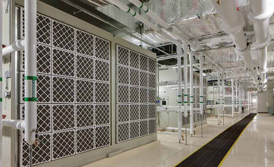
FIGURE 4. These AHUs in the mechanical gallery support the data center.
With these considerations in mind, air-cooled chillers were selected and sized to meet the critical cooling demand in peak summer months. The air-cooled chillers also addressed another concern with this mechanical systems approach, namely that smoke from a nearby structure or high levels of dirt from dust storms may impact data center operations. In these periods, the AHUs lower outside air to minimum levels to limit the impact of outdoor conditions on the building. The combination of chillers and fluid coolers then provide primary cooling for the facility.
Energy modeling at the time of design estimated that the proposed mechanical systems’ configuration used 58% less energy than an ASHRAE 90.1-2007 baseline system and operated with an annualized PUE of 1.2-1.3, consistent with current operations. While these systems use water to achieve a sustained high level of energy efficiency, they also save a significant amount of water as compared to the baseline mechanical systems. The Downtown Data Center is projected to save up to 10 million gallons of water annually when operating consistently with a 2.4-MW demand. These together with other design elements allowed the facility to achieve LEED 2009 Commercial Interiors Gold Certification in August 2013.
Power is delivered to the site from two separate sub-stations for concurrent maintainability and is tied together in isolated, rated electrical rooms in the electrical gallery located adjacent to the IT equipment and on the opposite side of the mechanical gallery. Standby generators support continuous operation with a loss of normal power via a series of automatic transfer switches. Generators then have the capability to continue providing power to the facility for up to a few weeks.
Prior to serving the IT equipment, power is fed through isolated uninterruptible power supply (UPS) units, each capable of operating up to 15 minutes on battery power to ensure a smooth transition from normal to standby power. Overhead busways above the IT cabinets support varying rack densities with minimal field modifications. Telecommunications are similarly racked overhead. The hot aisle enclosures above the racks utilize clear plastic sheathing to increase visibility and enhance hot aisle lighting levels.
In the process of consolidating these distributed production centers, the Downtown Data Center (DDC) transformed university operations. With the limitations of the production centers gone, flexible infrastructure, and room to grow, the DDC is enabling other university programs to flourish.


