


When WSP was asked to upgrade the central emergency power plant (CEPP) for VCU Health System’s downtown medical campus in Richmond, Virginia, we knew a detailed phasing plan and sequence of operations would be critical to the successful execution of the project.
The project’s campus generator plant was designed to provide a centralized emergency power supply (EPS) to distribute essential power to multiple hospital buildings across the urban campus. However, as the health system, and subsequently the campus, expanded to operate additional facilities in downtown Richmond, the operational capabilities of the plant would require upgrades to sustain the growth and desired redundancy.
CEPP Existing State
The proposed plan presented to VCUHS was to create an additional level of redundancy, control, and expandability to future-proof the campus’s EPS to align with the foreseeable campus master plan.
The first step in the process was to evaluate the current state of the campus from a loading perspective. In its existing state, the CEPP served the generator plant itself and two additional facilities: the main hospital and critical care hospital. Other major clinical facilities on the medical campus, including the clinical support center, north hospital, gateway, and ambulatory care center, were all provided emergency power by smaller generators installed at the facilities they served.
With four existing 1,750-kW generators installed at the CEPP and the various smaller point-of-use generators placed throughout the medical campus, the existing EPS displayed the capacity to support the existing loads. However, what was lacking in this scenario (one all too familiar to growing medical campuses) was a clear path forward for future expansion and proper redundancy.
Redundancy is a vital aspect to consider when evaluating system infrastructure on a medical campus with critical care facilities. In our case, it was observed with an existing load of approximately 1,720 kW connected to 7,000 kW of emergency power supply at the CEPP, the plant was heavily under utilized. This was easily identified as a missed opportunity to take advantage of N+1 redundancy at the plant. Even with four generators connecting in parallel, the absence of a tie circuit breaker at the generator paralleling gear resulted in the system being connected to a single bus. The system’s single bus was identified by the project team as a potential nonredundant point of failure and limiting the capacity of the Priority 1 loads of the system.
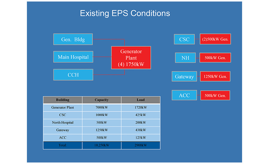 FIGURE 1. Existing EPS conditions at VCU Health System’s downtown medical campus. Photo Credit: Taber Andrew Bain
When it comes to engineering systems in the built environment, we understand there is an associated risk with a single point of a failure condition. However, we also understand that redundancy comes at a premium in terms of project cost and often real estate due to increased area requirements for the equipment footprint. It’s important to evaluate the risks in terms of cost-benefit to our project partners and clients so a collective decision can be made. In the case of a paralleling generator system with N+1 capacity, it would be considered high value, or “low hanging fruit,” to provide switchgear with the proper controls and a tie circuit breaker to allow generators on either the A or the B bus to supply the load on either side of the bus as a means for redundancy.
For the VCUHS emergency power upgrade, we received approval to proceed with the proposed solution of modifying the existing switchgear bus as shown in Figure 2. The solution provides a tie circuit breaker as well as A & B feeders to each facility for N+1 redundancy.
Identifying Challenges and Developing a Plan
Designing the system components is not always the most challenging aspect of an infrastructure upgrade project. What can determine the success or failure of the project, particularly in a mission-critical or critical care environment, is developing a plan and sequence for the work to take place while minimizing the disruptions to the service.
-
In what sequence would the project be built to allow for minimal disruptions of service?
-
If disruptions are necessary, how will temporary service be established?
-
How do we perform proper start-up and testing of the new system while maintaining the required emergency power for the campus to be operational?
-
Is this the most direct approach, and one that can be executed by the contractor?
-
What’s the future state, and does our design reasonably accommodate that modification?
Asking ourselves what the challenges would be prior to putting pen to paper allowed us to design in a manner that was informed by the means in which we would address these challenges.
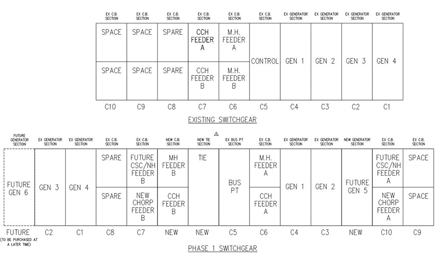 FIGURE 2. Existing vs. proposed phase 1 switchgear elevation. Photo Credit: Taber Andrew Bain
Our plan to rearrange and add sections to the existing switchgear created a challenge in respect to maintaining service while allowing for the contractor to most safely work on the gear. A process that relied on multiple “start-stop” phases of construction would create a drawn-out and expensive construction schedule. To account for this, a temporary state was developed where the existing generator switchgear could be bypassed, allowing for each connected facility to be served by one generator. Power feeders and controls were routed to bypass the paralleling gear and connect directly to temporary disconnects at the generators.
In our case, it was fortunate that each existing generator could carry the load of a single facility independently. If this had not been the case, a plan involving temporary generators or transformers would have needed to be developed.
A step-by-step sequence of operations should be developed by the engineering team and provided to the contractor to ensure these type of temporary condition plans can be correctly implemented. It is not to say the contractor will not provide alternate solutions, but it is recommended that the engineer ensure at least one solution and path forward exists, and it’s clearly communicated or provided as part of the design documents.
Prior to finalizing construction documents, we also recognized that the system would need to be tested and commissioned prior to turning the modified plant back to the owner. Included in the phasing sequence were recommended steps to test the new switchgear and controls with two of the four generators connected at a time. Utilizing a scheme similar to that of the temporary state plan, we tested two of the four generators at a time, with the other two generators maintaining secured emergency power to the campus. This allowed testing to occur for independent components of the system in a step-by-step planned sequence without lengthy interruption of service to the medical campus. A load bank was staged outside of the CEPP to test the generator’s capability to energize the modified bus and supply the load adequately. The load bank also tested the new tie circuit breaker, controls, and load priority sequence of operations.
In an abbreviated format, the construction phasing plan developed by our engineering design team took shape as follows:
-
Phase I – Disconnect generators from paralleling switchgear and execute the temporary EPS plan;
-
Phase II – Modify switchgear and install new controls as designed;
-
Phase III – Preliminary start-up and testing of system components;
-
Phase IV – Final start-up and testing of full system; and
-
Phase V – Commissioning verification with the owner present.
It’s worth again revisiting the importance of a detailed phasing plan and sequence to be determined during design and not during construction. This enables the system modification design to go hand in hand with the construction phasing plan, increasing the likelihood that the design can be implemented in a logical sequence.
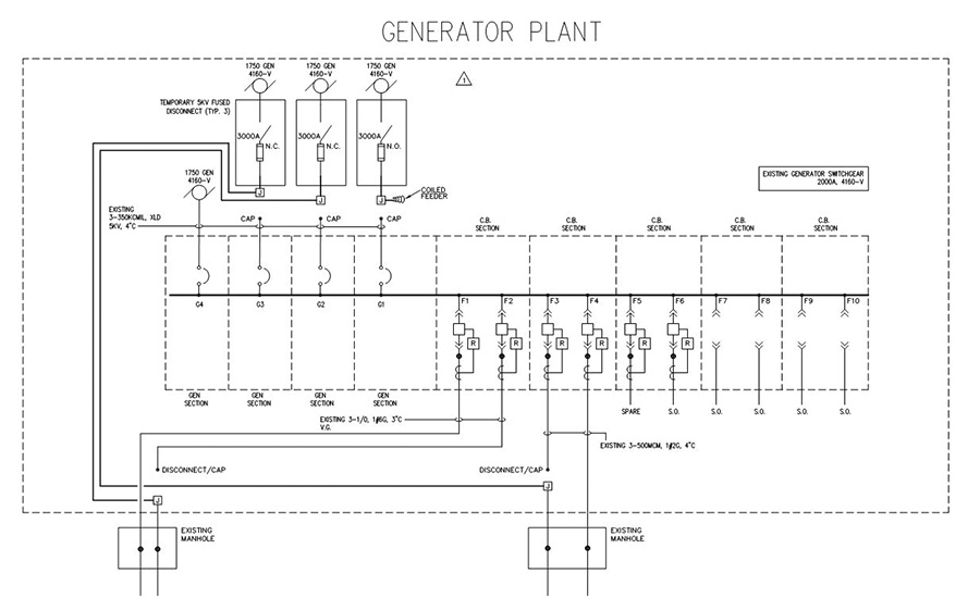 FIGURE 5. Temporary state one-line diagram. Photo Credit: Taber Andrew Bain
Implementing Solutions and Resolving for Future State
The design to upgrade the gear came to fruition after the engineering team observed the existing capabilities of the EPS and the arrangement of existing infrastructure. The existing conduits beneath the switchgear and feeders that are accessible in manholes outside of the CEPP were also observed and documented. With this information in hand, there appeared to be a path forward to modify conduits from the crawl space below and rearrange the current paralleling switch gear to allow for additional new feeder sections and a new tie circuit breaker.
The existing dual feeders to each facility were at the time served from the same switchgear section. The new design would relocate these feeders to opposite sides of the tie circuit breaker as part of the system upgrade objective to provide N+1 redundancy to these facilities.
A plan was developed for a new dedicated control lineup to be installed within the CEPP on the wall opposite of the paralleling switch gear. This control lineup provides master and auxiliary controls to the system and communicates with remote terminal units to be installed at the connected existing facilities as well as each facility connected to the CEPP in the future.
With the design in place for the new CEPP to provide N+1 redundant power to the facilities that were already connected to the old CEPP (main hospital and critical care hospital), we knew the job was only partially complete. The design would need to be modular and have a phased implementation plan to centralize the remaining medical facilities being served by the aforementioned point of use generator systems throughout the campus. This would mean not only provided space for future feeder circuit breakers but also for two future generators.
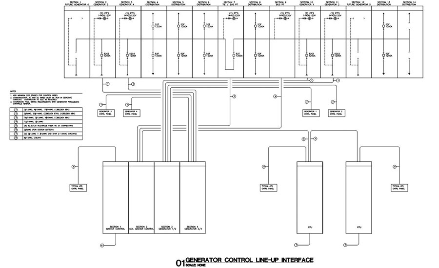 FIGURE 8. Control interface diagram. Photo Credit: Taber Andrew Bain
A plan was developed to expand the footprint of the plant in a direction that the existing infrastructure could accommodate without major reconfiguration of the equipment. Additionally, a phased future state implantation plan to centralize the EPS for the remaining existing medical facilities, as well as future facilities, was developed.
-
Current State Phase I – Interface the main hospital and critical care hospital;
-
Future State Phase II – Interface the north hospital and clinical support center;
-
Future State Phase III – Interface the gateway building;
-
Future State Phase IV – Interface the ambulatory care center;
-
Future State Phase V – Interface the known future children’s hospital; and
-
Future State Phase VI – Interface any unknown future facilities and install additional two generators.
Providing a clear path to future implementation allows for future consolidation projects and expansion without complicated phasing and shutdowns. Extended shutdowns can be crippling to a large medical campus, where downtime in any capacity should be avoided.
Conclusion and Acknowledgements
With time invested in developing a methodical phasing plan for construction, and also for implementing a phased future state approach, it’s possible to break down the seemingly daunting task of centralizing utilities in an urban environment to smaller, digestible pieces. It’s important that these pieces can be understood by the engineering team, the owner’s stakeholders, and the construction team, so the solution can be collectively implemented.
We were fortunate to have a great team on our project at VCUHS. The plant was successfully designed, built, commissioned, and is currently operational. Additional projects and new buildings have been since connected to the power plant as anticipated, with controls interfaced via remote terminal units and fiber-routed back to the plant.
 FIGURE 9. A future state phase IV diagram. Photo Credit: Taber Andrew Bain
Special thanks to VCUHS for the opportunity to partner on the project and the VCU plant operations and facility engineering team for their involvement and insight throughout the process. Thanks to George Campbell, P.E. for the thoughtful design review.


