

As the learning curve for VRF continues, it’s only fitting to see how it can fare in a familiar learning environment. Turns out it can play a key role in the critical lesson of adapting to existing spaces and occupancy needs when crafting the optimum retrofit design for a given client.
The advent of small-capacity, variable speed refrigerant compressors provide opportunities to design and install highly-efficient, controllable HVAC systems — making variable refrigerant flow (VRF) systems more commonplace within the industry. While they began with focused attention to the office and light commercial market, VRF systems can be applied to the institutional market.
Originally developed in Europe, these systems are designed for efficient power consumption, flexibility, a high level of zone control, and options for simultaneous heating and cooling. These features are very appealing to the education market, offering school districts an alternative to conventional all-air hydronic systems normally employed in colder climates. Although somewhat more complicated than conventional air handling/unit ventilator systems, VRF systems offer solutions that can meet some rather unique requirements.
The challenge
CannonDesign recently completed a major renovation and classroom addition at a 60-year-old school building that housed 500 students in kindergarten through sixth grade. This one-story school was the center of the community and, with low-slung sloped roofs, it blended in to the neighborhood. With a distinctive design, the school offered a warm and friendly atmosphere for this developing population — yet some students were located in temporary classrooms when capacity outgrew the existing building. The district realized it was time to renovate the building while providing additional spaces for the anticipated 550 student population in appropriately sized classrooms. The renovated facility now includes a swimming pool, conventional classrooms, a science/technology/engineering/math (STEM) specialty classroom, kitchen, cafeteria, and upgraded staff and teacher support spaces.
With an active setting filled with afterschool and evening activities, the facility needed to provide an improved indoor environment. The existing heating- and ventilating-only system was beyond its remaining useful life. To complicate the construction phase, the school had to be fully operational during the entire project, so well-planned phasing was critical without adversely affecting the school’s operation.
The selection of a VRF HVAC system with heat-recovery ventilation was based on three major factors.
-
Physical constraints to house HVAC equipment within the building
-
Phasing requirements
-
Simultaneous heating and cooling requirements
The school district required a high degree of space flexibility to accommodate its diverse activities, with requests for simultaneous heating and cooling year-round. Summer programs included educational and community events, so air conditioning was highly desirable. Because of the building configuration and exterior exposures, summer/winter changeovers would be problematic. Also, there was little opportunity to conceal ductwork above ceilings in the existing, low-profile building, except in the new addition. Roof-mounted equipment on the existing sloped roof was not feasible without adversely altering the building’s street-level appearance.
Space for HVAC equipment within the existing building was also at a premium. Two basement-level mechanical rooms housed gas-fired furnaces for heating and ventilation. All existing ductwork was installed within limited access crawl spaces. No space was available at grade.
There were four main construction phases for this project. Each of the four phases required removal of existing systems and completion of new systems — so each building portion could be occupied and meet safety and thermal conditions including ventilation.
In consideration of the building’s architectural appearance and an effort to maintain a clean look, all exterior HVAC equipment needed to be strategically located. The roof addition was designed to accommodate new HVAC equipment to its maximum potential.
The solution
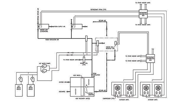
The challenge was met by installing multiple VRF systems providing heating and cooling, while utilizing the existing basement mechanical spaces to house ventilation equipment. Classrooms required 15 cubic ft per minute, per person, of ventilation air, with individual controls for both heating and cooling. Other spaces such as the cafeteria, library, and gymnasium/auditorium also required individual controls. In all, seven separate VRF systems were installed along with three air handling ventilation systems with heat recovery capability. This configuration of separate systems accommodated the phased renovation. Multiple VRF systems were selected for various building wings.
The indoor units consist of one- to four-ton nominal indoor units, with some conventional wall-mounted and console units serving offices, cafeteria, hallways, and adjacent spaces. The classrooms are conditioned by either three- or four-ton horizontal indoor units, depending on the classroom size. Systems within the existing building are concealed and located in soffits, built to mimic the original construction and complement the partly sloped ceiling following the roof line. The new classrooms accommodate the indoor units above the ceiling. Other building spaces contain either wall-mounted or console indoor units strategically located to provide heating and cooling.
In all cases, refrigerant piping is either concealed within ceiling spaces or in the building’s crawl space. As each indoor unit is piped with two lines, careful planning of the piping configuration and routing were required — with piping installed in groups on common supports. The crawl space was utilized as much as possible, since it lies beneath the entire building and provides an advantageous locale for the piping arrangement required from the outdoor to indoor units. Corridor ceiling spaces in the existing building conceal piping serving the soffit-located indoor units.
Ventilation
Ventilation is introduced to all spaces in various ways. The existing classrooms were previously heated by a hot-air system with supply air delivered through outlets integrated in outside wall bookshelves. The ductwork, located in a crawl space, was cleaned and resealed. It was then reutilized as the return-air path back to the heat recovery ventilation units. The new return-air grills are also integrated in to replacement bookshelves. The end results are completely renovated classrooms with similar appearances to existing conditions.
Conditioned air is delivered to the inlet of indoor units then mixed with air — heated or cooled — then delivered at the appropriate temperature. Corridor ceiling space below the sloped, peaked roof was just enough to accommodate the supply air ductwork.
Other spaces (offices, cafeteria, hallways, gymnasium/auditorium) receive ventilated air directly from the ventilation equipment located in the basement mechanical room through new or existing ductwork. This neutral air is also returned to the ventilation equipment through ductwork in crawl spaces. Various indoor units also condition these spaces by recirculating the air within the space, and they can either heat or cool in the same manner as the classrooms.
Responding to the challenge
VRF systems can offer a good option in PreK-12 settings. This experience demonstrates that when heating and cooling loads are matched up to indoor unit capacities, heating and cooling capabilities can take place through the refrigerant in relatively small piping rather than ductwork. Ventilation requirements can be accommodated by separate dedicated systems. In this scenario, pre-heated ventilation air, by heat wheels in the ventilation units, is further heated in hot water reheat coils. The hydronic system is also sized to provide enough heating in the event of a power failure where the VRF system would not be operable. The concept of distributing heating and cooling through piped hydronic systems are very conventional. VRF functions in much the same way, but the refrigerant distributes the heating and cooling rather than water.
The total installed cooling capacity for this system is nominally 140 tons, equivalent to 400 sq ft/ton. With the combined heating capacities of VRF equipment and hot water boiler heating system, the heating capability matches the school’s needs — and both heating sources operate in tandem.
From the client’s point of view, the equipment locations do not pose a maintenance issue as the indoor units are accessible and the outdoor units are either at-grade or on the new roof addition. The existing roof is kept clear, and the building’s exterior appearance is virtually unchanged.
Summary
The challenges that existed at the project’s beginning were met as follows.
-
Simultaneous heating and cooling. VRF systems have this option. Close attention to the heating capacities in northern climates is of utmost importance. In the heating/cooling mode, energy is essentially transferred from space to space by the refrigerant before compressor operation is required.
-
Limited ceiling space. The VRF indoor units are relatively small and essentially consist of a fan coil unit with a refrigerant coil that acts as either an evaporator (cooling mode) or a condenser (heating mode). They can be installed above limited clearance ceilings or exposed in the space as wall mounted or console units.
-
Exterior appearance. The outdoor units house the outdoor coil that operates as either an evaporator (heating mode) or condenser (cooling mode). They are relatively small in size and can be piped in parallel to provide the system capacity required.
-
Phased installation. Seven separate systems are installed to accommodate the phasing requirements, but also important was the relationship between the spaces to be conditioned to the location of the outdoor units.
-
Diverse school functions. Based on what activities take place within the building, the temperature control system can set up or set back temperatures of the separate systems. This feature can accommodate the use of parts of the building without conditioning the entire facility. The energy efficiency of the simultaneous heating and cooling in heat recovery mode is enhanced by the simple fact that zones in the building that are not being used can be conditioned appropriately while spaces in use are conditioned based on need.
Lessons Learned
VRF systems that include multiple indoor units in a system require critical layout and sizing of the refrigerant piping. Equivalent pipe lengths need to be kept within the system capabilities. Each indoor unit is connected with two dedicated lines that are then connected to the refrigerant branch selector box. Manufacturer’s requirements need to be followed.
-
Location of outdoor units in regard to distance from the refrigerant distribution boxes is also critical. Again, the manufacturer’s requirements need to be followed.
-
Space for the branch selector boxes is required, and they need to be accessible for maintenance. The location of this equipment should be determined during the design.
-
Each indoor unit acts as a cooling unit, and thus the condensate that forms needs to be drained away. It is very important that the drain piping is sloped and sized adequately.
-
Refrigerant piping is extensive in multiple indoor unit systems and requires space, especially where multiple indoor units are served in close proximity. Though the individual lines serving each unit are relatively small, with insulation and support attachments, the space needs can be more than expected.
Overall, the VRF system with heat recovery ventilation and a small hydronic supplemental heating system met the needs of the building HVAC requirements, allowing installation in conjunction with a phased construction/renovation so students, staff, and teachers continued their important work with limited disruptions.


