
figure
1. Dedicated
outside air ventilation system (DOAS) schematic.
From temperature differential’s effect on pumps over to an airside design that covers all the bases for comfort and efficient ventilation, the authors are combining preparation and innovation to give Tuscaloosa’s new federal building a suitably exemplary feel.
The new federal building in Tuscaloosa, AL, will become a symbol of innovation, sustainability, and energy savings for governmental buildings as it embraces several governmental and national standards and initiatives. One of these is the General Services Administration (GSA) requirement of 20% less energy usage than ASHRAE 90.1 as stated in the P-100-2005; however, the GSA-Region 4 has more stringent energy goals. In order to meet Region 4 requirements, the project team incorporated some additional solutions.
CENTRAL PLANT COOLING SYSTEM STRATEGY
The cooling system consists of two 220-ton water cooled centrifugal chillers, each sized for 60% of the cooling load peak. The additional 20% cooling capacity is an owner requirement for future expansion. The centrifugal chillers are equipped with three-stage compressors and VSDs to achieve 0.6 kW/ton peak load efficiency and an NPLV of 0.4 kW/ton maximum.The chilled water loop is a variable primary loop with three variable-speed pumps (330 gpm each, one standby). A bypass with flowmeter is provided to maintain minimum flow in the chillers as required by manufacturer. The chilled water temperature difference across the chillers’ evaporators is designed for 16°F. Higher temperature differential provides less water flow and less pumping power, resulting in improved overall system energy efficiency.
The condenser water system consists of two induced-draft, counterflow cooling towers with variable-speed fans. Three condenser water pumps are provided (660 gpm each, one standby).
The chilled water system is provided with a waterside economizer (WSE) in lieu of airside economizers. The decision to use the first option was made early in the design phase, since the AHUs are placed in the basement. Typically, an airside economizer will have a duct providing outside air nearly equal to the supply air quantity.
The duct sizes required to provide this quantity of air to the basement greatly increases the size of the shafts. Also, the airside economizer will require large relief air ducts and associated louvers. So, having an airside economizer will create complexity to the architectural planning and decrease the horizontal efficiency of the building, resulting in footprint increase.
In addition to those complexities introduced by airside economizers, they can affect the IAQ of the building, since the outdoor air houses a large number of airborne particles such as pollen, dusts, fumes, spores, and mold. This impact is minimized when using the WSE. For the minimum outside air quantity requirements, dedicated outside air ventilation systems (DOAS) are used. The outside air path has 35% efficient pre-filter and 85% efficient after-filter before entering the occupied spaces.
Although ANSI/ASHRAE- Standard 90.1-2004 does not require this project to have an economizer because of its location in a 3a-climate zone, the project team concluded an economizer would be beneficial to the performance of the building. Energy simulation and lifecycle cost analysis was performed and reflected an estimated savings in the utility bill of $15,223/yr, with an estimated simple payback of 4.1 years for the WSE.
The WSE cycle is achieved by means of plate-and-frame heat exchanger and automatic valves for changeover when outside air conditions permit. The water from the cooling towers is not, and should not, be circulated through the chiller’s evaporator because of concerns about fouling the system. The approach used to select the exchanger type was based on low pressure-drop, which was 10 ft of water. Typically, 10 to 15 ft of water-pressure drop is preferred. To assist in transition from economizer to chiller operation, the chillers are piped with head pressure control valves at the condenser water connections.
To maximize the use of the WSE cycle, it is designed to start at outdoor conditions of 45° wetbulb and 50° drybulb, and it should cut off whenever the chilled water supply temperature exceeds 52° or whenever the outdoor condition exceeds 60° drybulb.

Figure
2. An
artist’s rendering of the proposed federal building in Tuscaloosa,
AL.
HOT WATER HEATING STRATEGY
The hot water for the DOAS units’ preheat coils is provided by two (220 kW) condensing boilers (each boiler is sized for 67% of the full preheating load) and two 51 gpm, line-mounted, close-coupled pumps. The hot water system is designed for 130° supply temperature and 95° return temperature. The condensing boilers require a return-water temperature of 95° or less to achieve the published 95% efficiency rating.The reheating of air at the space levels is handled via electric reheat. This feature will provide less maintenance and less disruption to occupants in case the boiler fails to operate.
AIRSIDE STRATEGIES
The airside distribution system consists of nine VAV chilled water AHUs and two DOAS. One DOAS serves the courtroom AHUs, and the other unit serves the AHUs that provide conditioning to the remainder of the building.These DOAS units include a pre-filter, enthalpy wheel for total energy recovery, a hot-water preheat coil, a chilled-water coil, and a variable volume supply air fan that provides conditioned outside air to the mixing box of each AHU.
The energy recovery system is an integral part of the DOAS units. The heat recovery portion consists of a total enthalpy wheel used to recover energy from the building exhaust and relief air to pre-condition the outside air supply to the DOAS units. Total enthalpy wheels are selected for 85% effectiveness.
The amount of outside air provided to each AHU is modulated by means of a damper on each AHU’s mixing box to maintain the setpoint at a CO2sensor mounted in the common return duct of each respective unit.
The supply fan on each outside air unit is modulated to maintain static pressure setpoint in the supply duct. The supply fan static pressure setpoint is reset until at least one damper is 95% open. In addition, spaces with densities in excess of 25 people per 1,000 sq ft have been provided with space CO2sensors. In the event that these space-mounted sensors indicate an excess of the allowable limits in parts per million of CO2, the terminal unit serving that space increases the airflow to compensate.
If the terminal unit is unable to maintain CO2levels in the space at maximum airflow, the BAS increases the outside air supply to the AHU incrementally to maintain space requirements. The CO2levels inside the spaces as well as in the return air ducts are set for 700 ppm greater than the outside air CO2readings with a maximum setpoint of 1,100 ppm.
Minimum outside air turndown values are also maintained to offset the building exhaust to ensure that the building maintains a positive pressure with respect to the outdoors to limit infiltration. During unoccupied hours, the DOAS units provide 100% conditioned outside air directly to the space to maintain building pressurization.
These units also include a variable volume exhaust fan that is used for recharging the enthalpy wheel for total energy recovery. This fan is modulated to indirectly maintain a set static pressure in the space to maintain positive pressure in the building while also maintaining constant volume exhaust airflows in the restrooms as determined by duct-mounted airflow monitoring stations (Figure 1).
Static pressure reset strategies are used on the variable volume exhaust fan as well. Design ventilation rates are based on ANSI/ASHRAE-Standard 62.1-2004, “Ventilation for Acceptable Indoor Air Quality,” which varies the cfm/person and per area requirements depending on the occupancy type.
The AHUs for the building include MERV 8 pre-filters, a chilled water coil, a VAV supply fan, and MERV 13 final filters. The filtration was selected in compliance with the owner’s requirements. The courtroom units also include humidifiers downstream of the final filters. The control sequence for the AHUs includes static pressure reset and supply air temperature reset.
The return air system for each AHU is ducted above the ceiling to limit noise transmission from adjacent spaces, and to monitor relative humidity and CO2levels in the building specific to the AHU serving the space.
All terminal units are pressure-independent variable or constant volume boxes. Reheat is provided at terminals as required. Due to the diverse tenant scheduling in the building, the BAS utilizes occupancy sensors that are installed as part of the building lighting system to determine occupancy of each zone. For interior terminal boxes, the BAS resets the terminal box setpoint to 0 cfm if all the occupancy sensors in the zone served by the terminal box indicate all spaces unoccupied for a period exceeding 15 min, subject to maintaining setback temperatures (high 82°, low 65°, both adjustable) in the space.
OTHER KEY ENERGY-SAVING FEATURES
In addition to the strategies mentioned above, several strategies have been adapted that have direct effect of the cooling and heating loads of the building such as a high-albedo Energy Star® roof with a U-value of 0.04 (Btuh/sq ft/°F); a high-performance wall envelope with a high solid-to-wall ratio and a U-value of 0.05 (Btuh/sq ft/°F); and high-performance glazing with U-value of 0.3 (Btuh/sq ft/°F), a shading coefficient of 0.43 and a solar heat gain of 0.38. Additionally, the lighting power densities are designed for 30% to 35% less than ASHRAE 90.1-2004.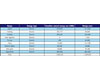
Table
1. Baseline
and design case energy use. Note boiler energy consumption was
converted from therms to kWh to simplify the data.
ENERGY MODELING
GSA had two goals for this building: use 30% less energy than a building meeting the minimum requirements of ASHRAE 90.1-2004 prescriptive requirements, and do not exceed energy usage of 44,000 Btuh/sq ft annually. The energy modeling results for both baseline building and the design-case buildings are shown in Table 1.With the building area of 123,375 sq ft, the energy use index of 34,681 Btuh/sq ft annually is achieved. Also, it is noted that this project achieves the 31% less energy use than ASHARE 90.1-2004. With the average electricity cost of $0.1025/kWh, the cost percentage savings are 31.15%.
CONCLUSION
The strategies presented in this paper combined with other sustainable strategies, such as reducing the water consumption by 40% relative to the Energy Policy Act of 1992 and the use of low-flow plumbing fixtures, will enable this project to attain LEED® Silver certificate under the 2.2 version, as well as to meet regional energy requirements of 30% less energy usage below ASHRAE.ESDisclaimer: The views expressed in the article do not necessarily represent the views of the GSA Agency or the United States Government.


