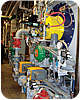
FIGURE 1 watertube boiler installation
Here, the manufacturer contemplates some possible ways that traditional flame scanners can wind up reporting a false flame status, followed by an outline of the company’s newest improvements in advanced flame detection.
Whether your plant has a single burner watertube boiler (Figure 1), single burner firetube boiler, or field-erected, multiple burner boiler or any other type of combustor, one question remains: How well are your investments protected?
The National Fire Protection Association (NFPA) Standard 85 and similar international standards partially address this concern by requiring flame scanning on burners and start-up burners for combustors firing a wide range of fuels to help protect plant equipment and personnel.1 Flame scanners detect the presence or absence of a burner’s flame in order to provide an input for a burner management system to control the state of the burner’s fuel valve. But how safe are the flame scanners supervising the burner’s combustion?
It is not uncommon to hear of a plant technician or operator shaking a flame scanner in front of a light bulb to get the flame relay to pull in; or taking a flame scanner off the burner, laying it on a bench only to have the sun’s rays provide enough signal to pull in the flame relay; or even performing weld inspections on an adjacent combustor, only to have the active combustor trip because the scanner’s sensor is being oversaturated from the X-rays. It is also not uncommon to hear about a flame scanner indicating a flame-on condition when in fact the scanner is reacting to the electromagnetic interference (EMI) generated from improper grounding, or hearing about a flame scanner indicating a flame-on condition when the burner is off but is seeing the signal generated from the hot refractory. All too often, these simulated flame signals can cause your safety system to become dangerously unsafe.
FLAME DETECTION METHODS
Currently, there are two methods of flame detection: physical and optical. Physical flame detection typically uses a flame rod that is biased with high voltage and is immersed in the flame when the burner is in service. In order to conduct a signal, the flame rod relies on a clean, large ground surface to allow a current loop to form through the ionization of the flame. All too often, the rod or ground surface oxidizes from byproducts of combustion (e.g., water vapor), high temperatures cause the rod to droop and ground out, or the insulation on the flame rod cracks, all causing the flame rod to become inoperable. Not only is a flame rod high maintenance, but it also requires high voltage of up to 280Vac in order to provide enough power for the current loop to form its way through the resistance of the flame. In an industry where low voltage is quickly becoming the norm, having 280Vac transmitted from the control cabinet through a cable to the flame rod in a hazardous location can seem undesirable.Optical flame detection typically uses ultraviolet (UV) and infrared (IR) sensors that react to the radiation emitted from a flame. UV tubes have been used commonly since the 1950s and are often biased with anywhere between 280Vac to 700Vac, depending on the manufacturer. UV tubes are known to fail over time and can fail in an unsafe manner, often referred to as a “runaway” tube. Electromechanical shutters are used to block the UV radiation to the tube and allow the amplifier to check for a runaway condition. Even with an electromechanical shutter, X-ray testing can cause a UV tube to saturate and trip a live burner. Self-checking UV scanners are required on burners that continuously fire without shutdown for more than 24 hrs. For burners that cycle at least once in 24 hrs, a UV tube scanner without the electromechanical shutter can be used. However, once every 24 hrs is a long time for fuel to build in the vessel if the flame has extinguished for whatever reason.
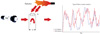
FIGURE 2 solid state sensor signal
circuit
There are many different sources that can simulate a flame signal, causing nuisance trips and putting equipment and personnel at risk of being harmed or destroyed. However, one flame scanner has been ingeniously designed to safeguard against these simulated signals: Coen Company’s iScan® flame scanner.
ADVANCED FLAME DETECTION
Years of troubleshooting these problems have lead engineers at Coen to design a flame scanner that actually differentiates real flame signals from simulated flame signals. First, Coen’s iScan® flame scanner combines the amplifier with the sensor. This allows Coen to eliminate the special “signal” cable previously required to run between the scanner and amplifier. With an independent scanner and amplifier design, the “signal” cable acted as an antenna for electrical interference. Having the sensor combined with the amplifier eliminates issues with EMI and RFI, and allows for a more pure flame signal to be processed. Combining the sensor and amplifier also allows the iScan® flame scanner to work off of 24Vdc; this eliminates the need for high voltages to run through cables that often jeopardized hazardous location areas and put service technicians at risk of being severely shocked.Second, the iScan® flame scanner uses a single solid-state sensor to detect both UV and IR radiation from a flame. In the industrial and utility markets, this is an important feature since a single scanner can be used in place of using one IR scanner for the oil flame and one UV scanner to monitor the gas flame. Because fuels change calorific values depending on where they originate, having a fuel-flexible sensor monitoring the flame is a real benefit. The use of a solid-state sensor also eliminates the need for an electromechanical shutter, since self-checking is done electronically and the solid-state sensor does not over saturate in the presence of X-rays or gamma rays.
Combining the sensor and amplifier into one housing, while using solid-state sensors, allows the iScan® flame scanner to eliminate a large number of risks that cause conventional flame scanners to become unsafe. However, it is the signal processing that is truly innovative. The sun, the operator, and the hot refractory can all still trick a flame scanner into indicating a flame is present when it is actually not. Coen’s iScan® flame scanner provides the market with a safety device that truly addresses these sources of simulated flame signals through four individual safety rules.
This flame scanner also monitors the rate of combustion by analyzing the flicker frequency, or the fingerprint, of the flame. Peak flame intensity occurs at stoichiometric combustion and drops off in a bell curve as the combustion becomes rich or lean. As the fuel and air mix and combust under the right conditions, heat and radiation are emitted in proportion to the fuel/air ratio. Since the premix burner flame is always burning back to the fuel source, the flame is always in motion. This motion allows the intensity of the flame to vary across a flame flicker-frequency spectrum. The iScan® flame scanner analyzes the flame flicker-frequency spectrum to determine what the fingerprint of the flame actually is. This flame scanner then compares the fingerprint of the flame with any other signals, whether real or simulated, to safely determine if the flame relay contact should be energized.
The iScan® flame scanner’s safety aspect really comes into focus because of the four rules that work in combination with the fingerprint of the flame. The first one is the “mains rule,” and ensures ground loops or improper grounding cannot simulate a flame signal since the line voltage frequency is concentrated at either 50 Hz or 60 Hz. The second rule is the “flame rule,” which ensures that only linear flame signals (starting at a high intensity, low frequency and ending at a low intensity, high frequency) are recognized as a flame signal. The third rule is the “solar rule.” This rule ensures the radiation from the sun will not be detected by the sensor as a flame signal. The “rail rule” safeguards against operator error in that a high gain setting in combination with the high intensity from the flame, will not allow the iScan® flame scanner to indicate flame-on. With the iScan® flame scanner incorporating these safety features, your plant can be ensured maximum flame supervision.


