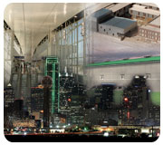
The building envelope at Dallas-Fort Worth International Airport’s Terminal D is roughly 50% glass, which delivers an open feel and plenty of natural light, but it also presented some HVAC design challenges. Discharge louvers were placed 29-ft above the floor to stratify the air and keep the floor cool (Photo courtesy of the Fort Worth Convention & Visitors Bureau).
Now Boarding In Terminal D...
Based on 2004 data from the Airports Council International, Dallas/Fort Worth International Airport (DFWIA) is among the busiest passenger airports in the world, having transported 59,064,360 passengers in 2005. It’s also the fourth largest in the world with a ground area larger than the island of Manhattan.DFWIA opened in 1973, and from its earliest design stages, Fort Worth-based Friberg Associates Inc., (under a previous corporate name - Cowan, Love and Jackson) had been involved with its HVAC systems. The firm helped design the original four terminals and in subsequent years worked on several projects at DFWIA.
Thus, when design work for a new Terminal D commenced in May 2000, it was no surprise Friberg Associates was selected as the MEP EOR for the terminal building and the sky bridge and hotel within it. The firm joined a team including the airport managing architect, HKS, Inc., Carter & Burgess, and other area engineering firms, and its Fort Worth office served as the headquarters for the all of the project’s design engineering work.

With its main hub located at the Dallas-Fort Worth Airport, American Airlines has traditionally exerted a lot of influence at the facility. The airline has always requested a 72°F interior design temperature, which has allowed passengers to be comfortable year round. (Photo courtesy of the Fort Worth Convention & Visitors Bureau.)
All For A Few Days A Year ...
The Dallas-Fort Worth area typically has a good year-round climate with only a few days of weather-related aviation problems annually. Of course, the local climate is very warm in the summer with typical design temperature of 100°F and 78°wb. The winters are generally mild, but there are cold days, with the winter design temperature being 17°. Thus, adequate heating capacity was required although it would be used very few hours annually with the internal loads of the airport.Friberg Associates had to deliver an HVAC system that met the owner’s requirements on the hottest and coldest days of the year as well as provide an economic system during the largest and more temperate part of the year. DFWIA has been significantly influenced by American Airlines, which has its largest hub at DFWIA and has always requested a 72° interior design temperature.
This temperature works quite well, according to Emil E. Friberg, P.E., president of Friberg Associates Inc. “For many years, North Central Texas enjoyed extremely favorable natural gas and electric power rates. In the last few years, there has been greater escalation than ever before in spite of, or perhaps because of, electric deregulation, so the owners have become extremely interested in the economy of the HVAC system.”
When it came to Terminal D’s HVAC design, the Dallas/Fort Worth International Airport Board (DFWIAB) demanded energy efficiency that would meet the International Energy Conservation Code while also planning for future flexibility in the interior of the building.
The new terminal building is approximately 2 million sq ft in comparison to the four existing terminals, which are around 700,000 sq ft each. It has a landside elevation that is semi-circular with driveways at multiple levels for arriving and departing passengers, as well as a service level. The airside of the building is rectangular in order to allow a longer perimeter than the semi-circle, so that additional gates could be added. The gates are designed for larger aircraft that typically fly international routes.
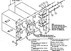
FIGURE 1. A coil diagram with a temperature differential of 28°F from Terminal D at DFWIA.
Studying The Footprint
The building has five levels, beginning with the service level, which is below the level of the ramp on the aircraft side, plus a hotel with eight guest floors, a lobby level, and a banquet/meeting level. The large footprint and the multiple levels of the terminal presented significant design challenges.The four original airport terminal buildings were designed with induction boxes, which turn down to approximately 40% of the cold air volume, then reheat with hot water coils. Over the years, in order to conserve energy, modifications and new systems included in the terminal buildings had transitioned to a single-duct side pocket VAV system with hot-water heat.
The new building’s upper walls are primarily glass (representing roughly 50% of the envelope) and while they deliver a pleasant open feeling, they also presented design challenges. “Because of these large volumes, it was determined that we would stratify the air, with the highest discharge louvers being approximately 29 ft above the concourse floor,” said Friberg. “This would leave a very large volume of glass that would seek its own temperature while the floor remained cool.”
A brief engineering study considered the possibility of a displacement ventilation- type A/C system; however, it was quickly discarded because of the amount of cooling required. In the two approximately 40,000-sq-ft concession areas, the terminal ceiling is approximately 71 ft above the floor. The bottom of the roof deck is 83 ft above the floor.
The smoke control in these areas was also done on a performance basis, which required numerous exhaust fans in the high roof. The large air volume above the level of the passengers provided a good space for smoke to be captured and exhausted, but the large spaces required a constant volume AHU in order to obtain a long throw performance with the grilles.
In order to achieve some economies in energy use, VFDs were included on all of the constant volume units so they could be turned down in the night. This strategy would likely sacrifice good temperature control in parts of the concession areas but allow economies when very few passengers were present.
The 9/11 Impact
“During the design process for the four original terminals of DFW, we decided to take outside air for the HVAC system only from the roof,” Friberg said. This minimized fumes from jet engines on the airside and cars/buses on the landside and proved quite successful.“For Terminal D, we were determined to follow this successful principle. As the design and construction were progressing, America experienced the 9/11 attacks. Thoughts soon turned to possible chemical and biological attacks. The airport staff was very relieved to hear that the outside air intakes were perfectly positioned to minimize the risk of a chemical or biological attack.”
As a result of 9/11, the structural design was made more blast resistant, which resulted in many challenges to fit well designed duct into smaller spaces. According to Friberg, this was a case where the HVAC engineers should really be called “space” engineers. “Our mission was to use reduced areas and still achieve good air conditioning,” he said.
In the Tarrant Regional Water District, totally enclosed water to air cooled (TEWAC) pump motors were selected over several other options to cool large water pumps bringing water from reservoirs to water processing facilities. Air cooled motors require a large dedicated AHU blowing cold air on each motor.
Terminal D ΔT
When the airport was originally designed, the four terminals were all served from a central heating and cooling plant located near the center of the airport between the main north-south entry roads. A unique feature of the central plant was the design for a 24°ΔT on the chilled water system, which worked well and produced large savings in pump energy over the life of the system.Terminal D’s design employed 38° entering chilled water and 66° return chilled water. When the new terminal design began, the designers who were renovating and providing additional capacity at the central heating and cooling plant requested that Terminal D be designed for 28° chilled water ΔT. With the new terminal at 28°, and most of the existing facilities at 24°ΔT, the few areas that could not be readily designed for that temperature differential would be offset by the loads in Terminal D and the chillers could actually see a 24° average temperature differential. “The AHU manufacturer working with the design team worked through some different coil designs and eventually we selected the design that was used at Terminal D and has provided temperature differential of 28°,” Friberg said (Figure 1).
Having opened in July 2005, Terminal D features the world’s largest high-speed airport train system (named Skylink) and has helped DFWIA to successfully continue moving people in relative comfort thanks to the careful HVAC design that went into the project.
Priming The Pumps For Progress
The Dallas-Fort Worth area faces some daunting water challenges and while it’s a bit off the beaten HVAC path, ensuring that the area’s water districts are up to the task of delivering the wet stuff to the endusers represents a formidable undertaking.Adjacent to Dallas County and home to Fort Worth and Arlington, Tarrant County is one of the fastest growing urban counties in the United States. The Tarrant Regional Water District (TRWD) is one district charged with meeting the water needs associated with this exploding population growth. The increasing demands on the City of Fort Worth’s water treatment plants have made it difficult to meet the demands currently served by other reservoirs. Thus, the TRWD has undertaken the Eagle Mountain Connection project, which will pump water from the district’s East Texas Reservoirs to Eagle Mountain Lake.
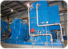
The Eagle Mountain Connection project consists of two pump stations, the Benbrook Booster Pump Station and the Rolling Hills Booster Pump Station. Each pump station has three main rooms: the pump room, the electrical equipment room, and the control room. The pump rooms are approximately 8,100 sq ft and house four to six pumps, ranging from 900 to 3,500 hp. Large suction lines tapped off of an 114-in.-dia suction header are connected to each pump and are discharged to a 96-in. dia discharge header that can take the water to multiple distribution points, such as water treatment plants or other reservoirs, depending on the need.
All but one pump has an associated VFD located in the pump station’s electrical equipment room where other electrical equipment such as motor control centers and switchgear is also located. The control room inside the pump station houses the SCADA equipment, which basically serves as the network for monitoring and controlling the pump station.
Fort Worth-based firm Freese and Nichols, which has had a relationship with TRWD for several years, was selected for the design. Jeff Hammond, P.E., C.E.M., the firm’s lead mechanical engineer for this project, explained that cooling the large pump motors in an energy efficient manner presented a major challenge. Additionally, with a design water temperature of 85°F, coordinating with the pump manufacturer’s flow requirements also presented some dilemmas.
The heat generated by the large pumps had to be removed from the pump room so the pumps wouldn’t exceed their recommended operational temperature limits. The firm devised several different design concepts for the pump room ventilation system.
An artist’s rendering of the Benbrook Booster Pump Station in Tarrant County. A duplex basket strainer catches the raw lake water entering the pump station before connecting to the TEWAC motor heat exchanger.
The Concepts
First, the team considered using exterior wall louvers and roof exhaust fans, which is a traditional approach to ventilating pump rooms. However, the size of the pump motors (3,500 hp) and the resulting concentration of heat generated, would have required an enormous volume of air to ventilate and remove the heat from the pump room, thus cooling was necessary in this application and not just ventilation alone.Also, the owner wanted the mechanical equipment to be easily accessible for maintenance access, which meant that roof placement was undesirable. Wall exhausters were also an option, but again, the size of the pump motors dictated that cooling be employed.
Exterior wall supply fans and roof relief hoods were also pondered, but since cooling was necessary, the option was only partially employed. Relief hoods were used to avoid mechanical equipment on the roof to deliver supplemental ventilation.
Air handlers using lake water that would be pumped through cooling coils would have been an energy-efficient choice. However, lake water levels and temperatures fluctuate throughout the year and with the peak operating months of the pump station being in the summer when lakes are around 85°, this design concept was eliminated.
Another option was using self-contained water cooled AHUs with lake water on the condenser side of the unit as the medium. Freese and Nichols have employed this energy-efficient concept on previous projects with similar large hp pump motors, and it would have been chosen had TRWD selected air cooled pump motors instead of water cooled pump motors.
However, following a cost analysis, TRWD elected to go with totally enclosed water to air cooled (TEWAC) pump motors. These 900- to 3,500-hp pump motors are water cooled, using the raw lake water that they are pumping. The lake water takes the heat from the motors, eliminating the need to air cool each motor. If the motors were air cooled, each motor would have required a large dedicated AHU blowing cold air on the motor.
“By using water cooled motors, we were able to go directly to the source to remove the heat and avoid having more equipment and the associated maintenance, ductwork, power, and space in the pump room required for the air handlers,” said Hammond. The TEWAC motors cost more, but saved TRWD considerable energy by using the lake water for motor cooling.
The Specifics
The cooling water piping is tapped off of a large discharge header downstream of the large pumps and routed through a duplex basket strainer before connecting to the TEWAC motor heat exchanger. Once through the heat exchanger, the cooling water piping is dropped back into the lake pumping system via the suction side of the pumps. Ash Deshpande, P.E., a Freese and Nichols senior mechanical engineer, designed the motor cooling system such that each TEWAC motor cooling piping branch is arranged with an on/off control valve and an automatic flow-balancing valve.At one of the pump stations there was concern that when only the low head pump was operating (900 hp), the head pressure would be insufficient. Deshpande designed a piping arrangement to include a small inline pump in the cooling water system to energize based on a signal from a pressure switch mounted in the cooling water supply piping.
Additional ventilation was designed using Greenheck wall supply fans and roof mounted relief hoods to ventilate the entire pump room. Wall-mounted thermostats with an 85° setpoint control the fans. The cooling design for each of the two electrical equipment rooms employed three 50-ton Trane packaged rooftop units.
Initial costs, operating costs, ease of maintenance, accessibility, previous project design consistency, and reliability were all important factors discussed with TRWD during the design phase. Eliminating large hp, energy-hogging fan motors from the design and incorporating the available natural resource (lake water) as a direct source for removing the heat from the pump station created an opportunity to be innovative and save energy.
“Energy-efficiency awareness has become increasingly important to integrate into projects, and we felt this was the perfect opportunity to demonstrate making energy conservation a priority in our design,” Hammond said.

The construction site photo illustrates just how “downtown” The Booker T. Washington High School for the Performing and Visual Arts (BTWHSPVA) is. The Arts District is to the right of the building (Photo by Jennifer Dye and courtesy of Thos. S. Byrne Ltd.).
All About Performance
Spanning nearly 20 blocks in the northeast portion of the city, Dallas’ Arts District is home to the city’s art museum, symphony, several theaters, galleries (including the new Nasher Sculpture Center), and a new opera house currently under construction. Amid this enlightened atmosphere sits yet another cultural beacon, The Booker T. Washington High School for the Performing and Visual Arts (BTWHSPVA).The school was the first institution in the Arts District and its only school. The building was constructed in 1922 as the first African American high school in Dallas. In 1955 additional space was added for vocational training when it became a technical high school. In the mid-’70s as a result of desegregation, the Dallas Independent School District (Dallas ISD) shifted the building’s focus by establishing the BTWHSPVA to meet the specific needs of gifted artists.
The school has produced a stellar list of famous graduates, including Grammy winners such as: Norah Jones, R&B vocalist Erykah Badu; jazz trumpeter Roy Hargrove; and Edie Brickell of the groupEdie Brickell and New Bohemians.
It attracts students from throughout the metropolitan area, and its multi-ethnic student body includes approximately 700 students in grades 9 through 12.
Art Factory On The Move
In January 2006, the school temporarily relocated to Nolan Estes Plaza in south Dallas so construction of a new building on the original site could commence. The original had evolved into a pieced together complex consisting of a landmark historic building, and multiple expansions of varied age, style, and quality. Dallas ISD sought a new facility that would better serve the needs of the students and better fit in with its surroundings.A national competition for architectural design was held, and Allied Works Architecture (AWA) of Portland, OR was selected to design the new facility in partnership with Booziotis & Company Architects of Dallas. G|S Consulting Engineers of Dallas was invited by AWA to participate on the project at the start of design in 2004 as the MEP/fire protection firm.
The primary architectural concepts for the facility positioned it as a “factory for art,” and the design team was directed to include minimal suspended ceilings, with most of the HVACR system exposed in the occupied area. Since concealed ceiling spaces were not available in most locations, the air distribution system was designed without significant horizontal distribution on each floor. The building was provided with seven vertical chases from the basement through the top floor, which allowed access to most of the spaces with a minimum of horizontal ducting.
“In order to keep noise down in each classroom, the system was designed with single duct VAV units, one per classroom, with electric heat and integral sound attenuation,” according to Cheryl Baylie, principal with G|S. To protect the ductwork, double-wall round or aluminum-jacketed rectangular ductwork was used in exposed locations.
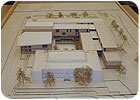
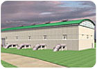
This model of the finished BTWHSPVA building shows the original building in the front and to the rear right of it is an “L”-shaped atrium of between three and four stories that was created as an open area for communication and creation with in the school (Image courtesy of Allied Works Architecture).
Preconditioned Reconditioning
The historic building was constructed in 1922, replacing an original building that was erected circa 1884 and known then as Colored #2. The name was changed to Booker T. Washington in 1902. The entire building is being reconditioned and refurbished to bring as much as practical back to its original architectural state.This original building was designed and constructed before the proliferation of commercial A/C and was designed to optimize natural ventilation. Suspended ceilings had been added in the interim to conceal central ducted air conditioning from AHUs on the roof. All of this is being removed, and the original high ceilings are being re-exposed. The original large double-hung windows are being reconditioned and reinstalled on all the perimeter spaces opening into the classrooms. The original transoms above all the interior doors allow crossflow into the corridors, which are laid out straight through the building with doors and windows at all ends to encourage airflow.
In a direction very unusual for a contemporary southern climate, these features are being resurrected and utilized to provide natural conditioning and ventilation for the building’s perimeter spaces. During most of the mildest weather, the building will be open to the sounds and smells of the Arts District, saving energy and money for the school district.
Due to the extended duration of the hot climate in the Dallas area, schools and learning centers are usually provided with A/C, and even the reconstituted historic building was no exception. It was important to maintain the visual impact of the original installation, so a perimeter heating and cooling system comprised of chilled water fan terminal units with electric heating is being located in approximately the original locations of the steam radiators, utilizing the steam and condensate chases for the chilled water and condensate piping.
Value Engineering KO's Gas
According to Baylie, the HVAC system was originally designed with a hot water system for heating, which would’ve included flexible watertube, natural gas-fired boilers in the basement. However, an all electric heating system won out in an early value engineering exercise that included input from Dallas ISD and several potential general contractors and subcontractors.The system was designed with three air cooled rotary screw chillers (three Trane units, two 350-ton and one 185-ton) serving the cooling system. Provided with hot gas bypass, these chillers can be staged to provide a high degree of capacity matching with a minimum of five full stages and part-load unloading within those stages. They are manifolded with a primary pumping station, which provides pumping redundancy. There are four primary pumps, two at 350 gpm and two at 700 gpm. “This size configuration provides additional redundancy with two smaller pumps able to be staged to replace one of the larger pumps,” Baylie said.
The chilled water system serving the air handlers is a single large secondary loop with three 900-gpm vertical split case pumps with VFDs for capacity control and energy efficient chilled water delivery.
Since the facility has only three levels above grade and is adjacent to important public venues, high-rise residences, and high-quality offices, it was important to keep the roof “clean” – free of HVAC equipment as much as was practical. All of the air-handling equipment (manufactured by McQuay) except exhaust is located in the basement. Baylie explained that it was necessary with the limited overhead space in the basement to select air-handling equipment that could be produced with shorter profiles. The AHUs were selected with plug-style fans for supply and return to keep units and associated ductwork profiles exceptionally compact while maintaining quiet and energy-efficient performance.
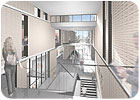
This 3-D rendering of a clerestory in the building conveys the open air feeling the designers sought (Image courtesy of Allied Works Architecture).
Facilitating Four-Way Communication
The school was also to be an area to cultivate an exchange of ideas between different forms of expression. Its common areas were designed to be open both vertically and horizontally. An “L”-shaped atrium of between three and four stories was created in the center of the building and required an engineered smoke control system, which Baylie called a “special challenge.”The space configuration was determined to be too complex for the simplified calculations to determine the proper system characteristics, she added. “We brought in a specialist sub-consultant to produce a 3-D CFD model of the smoke development to use to validate the design for the local fire department and code authority. Use of the model was integral in developing some architectural solutions that reduced the size of the installed equipment while enhancing the performance of the system.”
While the building isn’t expected to be completed until November 2007, the students and staff are eager to get into the new facility that’s been designed to optimize performance and comfort in this thriving section of Dallas.
