

Rack Loading
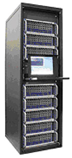
A typical rack or cabinet is 24- to 30-in. wide, 36- to 44-in. long and 76-in. high and can incorporate up to 42 U of computing equipment (Figure 1)."U" is a standard unit indicating the height of the computer server. Each "U" is 1.75 in. A 5 U server is 8.75 in. tall, therefore eight 5 Us fill a 42 U rack. Like most electronic devices, the processing power and space efficiency of the servers has increased considerably in the last several years. As the servers have become more compact and efficient, more servers can fit into the rack or cabinet rack. A casual glance at Figure 2 in ASHRAE's latest publication on data centers1 would give the impression that the rate of increase heat load per square foot of data equipment appears to be leveling off in 2005.
On closer scrutiny, the vertical scale is logarithmic, so that a straight line with a positive slope reflects an increasing rate of growth. A 42 U cabinet installed five years ago with three U servers has a total cooling load of 3 kW to 4 kW, about one ton in six sq ft. Today, the same cabinet can be filled with 7 U blade servers having a total power consumption over 20 kW, or more than 5.5 tons of cooling for the same six sq ft.
Satisfying the Needs for Higher Density Loads
Challenged with replacing older lower-powered computers with modern higher-powered equipment, IT and facility engineers are often faced with determining how to install the new equipment within the confines of existing power and cooling systems. Generally, if the servers are spread out by lightly filling the cabinets, cooling and power issues are more easily solved. If the cabinets are filled to capacity with the new high-powered servers, the computer room will have large open areas or "white space." This space cannot be occupied due to lack of power and cooling capability.A typical corporate data center can have several hundred cabinets. For example, a legacy computer room designed for 400 2.0-kW racks has an equipment-cooling load of 800 kW of cooling. If the legacy servers in the 400 racks are replaced with 200 racks at say 12 kW each, the equipment load increases from less than 250 tons to over 680 tons with half as many racks. If all 400 racks are upgraded to 12 kW, the cooling system capacity climbs to 1,365 tons! When planning for a new computer room, it is imperative to master plan for ultimate power and cooling capability as well as to set an upper limit on the maximum power consumption in a single rack or cabinet.
Overloading an existing system is not the only problem that high-density racks present. Even when cooling systems are sized properly for the high-power consumption cabinets, getting cooling to the servers inside the racks can be difficult. A computer room can be designed for an average load of 60 W/sq ft, but may not adequately cool a load that is not evenly distributed throughout the space. One end of the room may have tape drive equipment with a 20 W/sq ft load, while the other end is filled with high-density cabinets having a load of 120 W/sq ft. The space in between could be left unpopulated, with no load but a few watts per square foot for lights. If the design does not have the flexibility to provide more airflow to the heavily loaded areas, hot spots are unavoidable.
Just evenly distributing the high-density cabinets may not solve all the problems. A row of equipment 3-ft wide and 40-ft long with 20 cabinets each dissipating 10 kW is a lot of heat in a very small area. This row of cabinets can be repeated with 4-ft wide aisle spacing. Ten rows total 200 racks in less than 3,000 sq ft or about 5.3 sq ft/ton. Compare this to a typical office building around 300 to 400 sq ft/ton. The 3,000 sq ft with 200 cabinets needs over 80 cfm/sq ft based upon a 25°F differential temperature.
Computer rooms have always needed special cooling equipment to meet their high airflow requirements, but even with standard computer room cooling equipment, the high loads can be difficult to cool. Most computer equipment has maximum inlet air temperatures of no more than 95°. ASHRAE has recommended temperature and relative humidity guidelines to help engineers and facility personnel ensure computing equipment outages are not environmentally related2 (Figure 2).
Computer room cooling has generally been provided by A/C units known as computer room air conditioners (CRACs) or computer room air handlers (CRAHs). The terms CRAC and CRAH are sometimes used interchangeably. CRAH is a less common term and generally refers to a unit that has a chilled water coil and no compressor, condenser, or other refrigerant components. CRACs come in a variety of shapes and configurations, consoles, ceiling mounted, free-standing floor models, up flow, down flow, DX split systems with air cooled condensers, self-contained with water, or glycol-cooled condensers. Sizes vary from a ton to over 30 tons. Larger central station air handlers are also used and can provide additional flexibility when it comes to coil selections, fans, filtration, and energy saving alternatives.
In a typical computer room, cold air is introduced into a raised floor plenum. Perforated floor tiles discharge the air to cool the computer room. A perforated tile is 24 by 24 in. and has open free area of 25%. With a static pressure of 0.05, the perforated tile can deliver about 550 cfm. The cold air temperature is generally controlled to ensure proper environmental conditions at the air inlets to the computers.
A critical component of the A/C system is the raised floor plenum. The plenum must provide a path for the chilled air to the perforated tile and/or cabinet. The ability of the floor plenum to perform this function depends on the local static pressure in the plenum below the perforated tile. Ideally, the plenum static pressure is almost equal to the total pressure - very low velocity pressure. As loads increase, so do the required airflows, and higher airflows means higher velocities and bigger floor plenums.
Twenty years ago, 12- and 18-in. raised floor plenums were common. Today, 24 in. is the minimum depth, although plenums over 5 ft in depth have been constructed to accommodate very high airflow rates and large underfloor piping, conduit, and communication systems. Sealing the floor plenum to reduce leakage is also critical to ensure adequate cooling at design loads. Most of the equipment placed on the raised floor is provided with openings in the bottom for cabling or power conduit penetrations. If the openings allow air to return to the A/C units without providing the cooling to the equipment, cooling capacity is reduced.
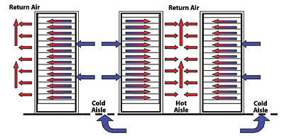
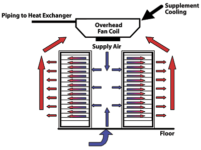
In a commercial type A/C system, cold supply air is inserted into the space via a diffuser or grille that rapidly mixes the cold supply air with the warmer room air. The temperature variation in the office areas is only a couple of degrees or less. In a computer room, however, the temperature variation can be much larger. One design approach is the hot aisle/cold aisle arrangement. This approach (Figure 3) arranges the computing equipment such that chilled air for all equipment in the row is introduced into a common cold aisle, and the hot air is discharged to an adjacent aisle.
This approach accepts the inevitability of significant temperature variations between the front and back of the cabinets and arranges the cabinets to get the maximum cooling to the computers. This arrangement works very well in many applications, but as the load density increases, so does the temperature gradient around the cabinets. Even with a hot aisle/cold aisle arrangement, not all the servers will operate at the same temperature. The natural mix of the airstream leaving the perforated tile creates a vertical temperature gradient in front of the cabinet; the closer to the top of the cabinet, the warmer the air.
Additionally, in higher density cabinet applications, the air requirements of the computers themselves are usually higher than that available through the adjacent cold aisle perforated tile. This generally results in recirculation from the hot aisle into the cold aisle. Often average cold aisle temperatures in the 60s are required to ensure satisfactory entering conditions to the computing equipment in the upper levels of the cabinets.

Computer Modeling
Due to the complex nature of the airflow patterns within the data center, it is becoming common practice for HVAC engineers to use computational fluid dynamic (CFD) modeling to predict the airflow in the computer room (Figure 4). These programs use finite element analysis to determine velocity pressure, flow, and temperature variations, presenting the results both graphically and numerically. CFD programs can present graphical results in either 2-D or 3-D format. The 2-D CFD programs model the raised floor plenum, analyze airflow patterns and pressure underneath the raised floor, and accurately determine airflow through the air devices installed on the raised floor. The programs offer a library of standard components such as servers, perforated tiles, floor grates, and CRACs/CRAHs. As well as facilitating the HVAC engineer in determining the raised floor height, these programs can assist in where potential hot spots could occur.
The 3-D CFD models the airflow both below and above the raised floor. With the 3-D program the user also inputs data on the room height, cabinet heat, and cabinet airflow, as well as all the information on the raised floor plenum. Both the time to input the data and the time to run the analysis is generally longer with the 3-D CFD, but significantly more information is provided about the airflow around the cabinets and in the computer room.
Floor Grates
In response to the high-density areas within the computer room, air supply manufacturers have introduced new products. One such product is a floor grate. These grates have a greater net free area than perforated tile, usually 56% to 60%. The higher percentage of area increases airflow, while reducing the pressure drop and air velocity. A floor grate without a damper can supply up to 2,000 cfm, as compared to a perforated tile's 550 cfm capability. When using these air devices, consideration must be given to discharge velocity to ensure the servers located towards the bottom of the rack aren't bypassed with the higher velocity air. Additionally, floor grate retrofit installations adjacent to, or in replacement of, perforated tile can significantly reduce the airflow through the perforated tile, possibly affecting airflow to adjacent computers.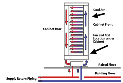
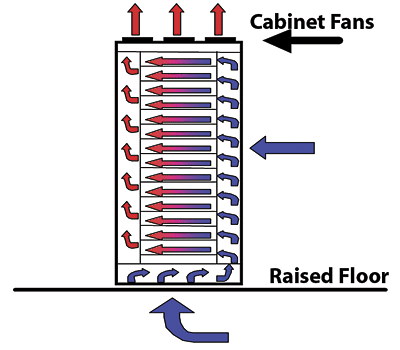
Cabinet Fans
An alternative to the hot aisle/cold aisle approach is to use cabinets with built-in fans (Figure 5).
The cabinets produce air directly from either the floor plenum or the cold aisle, and deliver the supply air to the equipment. There are many styles of cabinets available. The most common style has the fans on top with a vertical discharge of the hot air. Our recommendation is for owners/operators to test a cabinet with their specific computers at their design load densities to determine whether or not a particular cabinet type is appropriate for their application.
Other Cooling Solutions
As the cabinet loads climb above the capabilities of conventional air cooling, alternative cooling solutions using water cooled cabinets or local refrigerant-based cabinets are available (Figures 6 and 7).These cooling solutions have proven their capability to support cabinets at up to 20 kW. The refrigerant based fancoil approach places the fancoil units on top of, or in front of, the cabinets. Pipes deliver liquid refrigerant to the fancoil units. Not all the refrigerant evaporates at the coil and a liquid gas mix flows back to a condensing unit located either in or near the computer room. The condensing unit uses a heat exchanger to condense the gas and provide some subcooling to the liquid. This condensing unit operates at lower pressures than the conventional refrigeration cycle, and does not need a compressor, as chilled water is cold enough to condense the refrigerant. If chilled water isn't available, a separate refrigeration circuit can provide cooling to the heat exchanger.
There are two water-cooled cabinet styles currently available. The first incorporates a cooling coil mounted at the bottom of the cabinet in an air plenum and fans in the back of the cabinet to push the air through the coil and to supply air to the fronts of the cabinets. A plenum on the back is used to collect air and return it to the fan. The water circulating in the system should be above the dewpoint of the computer room to ensure that condensation does not occur in the cabinet. The second approach mounts the fan and fancoil to the rear cabinet door, drawing room air into the cabinet, where it is heated by the servers and then cooled in the coil and discharged back to the room.
As the cabinet loads go from 2 kW up to 20 kW and beyond, owners/operators and their engineers must do far more than specify these latter products. While the latest developments in cabinet and computer cooling may become common practice in the future, we likely will continue to push the envelope of design beyond the norm. When "pushing the envelope," there are few rules of thumb or precedents on which to rely. High-density data centers continue to be unique, with little published data on how large groups of high-power consuming cabinets are going to perform.
To maximize the likelihood of success in any computer room cooling project, the owners and their infrastructure designers, IT designers, and operators need to work together closely to develop the raised floor plan including computer types, average and spot power densities, cabinet types and layouts, and the arrangements of the supporting air conditioners and electrical equipment. Careful consideration and planning should be given to future growth and the required electrical and mechanical infrastructure systems required to support that future growth.
It is also worth mentioning that the efficiency of the server (switch-mode power supply) is 75% to 80% and greatly affects the cooling requirements. This is an area that server manufacturers need to address as well. ES
The Birth Of The Cool
One wonders how many computers have made the inevitable trek from the showroom or catalog to the scrapheap. However, before the equipment pictured here ever went on sale, the early computers were nearly as big as the scrapheap itself. Wringing heat out of these large supercomputers became a pressing concern.Early computer designer Seymour Cray had to pay great attention to cooling. In the case of the Cray-1, which looked like a loveseat of sorts, he obtained patents for copper tube extrusions into the aluminum cooling columns. Subsequent designs by Cray and others would use a non-conductive medical plasma substitute and even liquid nitrogen to prevent boards from overheating.
Even prior to those innovations, however, a more familiar name to the HVAC industry had embraced the task of getting past the custom of making a custom cooling/humidity system for each new computer room. Mechanical contractor Ralph Liebert created his prototype for a completely packaged system in 1964, allowing for time-saving "plug and play" installation, so to speak.
Liebert faced special considerations in designing for this relatively new application. Coil sizing had to account for the unusual sensible heat loads. A downflow air pattern gave the unit entry to the computer room itself, where it eliminated ductwork by directing air beneath the raised floor. Semi-hermetic compressors, humidifiers, and electric reheats teamed with custom controls to meet the high tolerances involved.
After tinkering with the component locations to allow for adequate service access, Liebert took his work to the World Computer Conference in 1965, and displayed it in cooperation with IBM. Interest there spurred Liebert to start a corporation specifically for such products.
In subsequent decades, computers, computer rooms, and their temperature control needs have proliferated faster than you can say "five-inch floppy disc." But forty years ago, the whole endeavor seemed so out of the mainstream, and it took solid engineering, of all things, to make computers cool.
The Birth Of The Cool
REFERENCE
1 - "A Walk Through Visible Storage", section 3 of 6, by Len Shustek, from CORE 2.3, a publication of The Computer History Museum. Found online at http://ed-thelen.org/comp-hist/Shustek/ShustekTour-03.html.

