
There’s a debate among commercial and industrial hydronic system designers: how best to refine and enhance pumping and system efficiency to precisely match output to load (need). Decades ago, primary-secondary pipe and pump arrangements emerged as state-of-the-art.
Invariably, new thinking and technology conspire to replace established standards. What emerged — to favor system performance as well as fuel and electrical consumption — is a variable speed/variable flow approach.
A primary-secondary system pumping strategy provides a primary “river” of thermal energy (heated or chilled water) connected to secondary tributaries that serve system distribution zones.
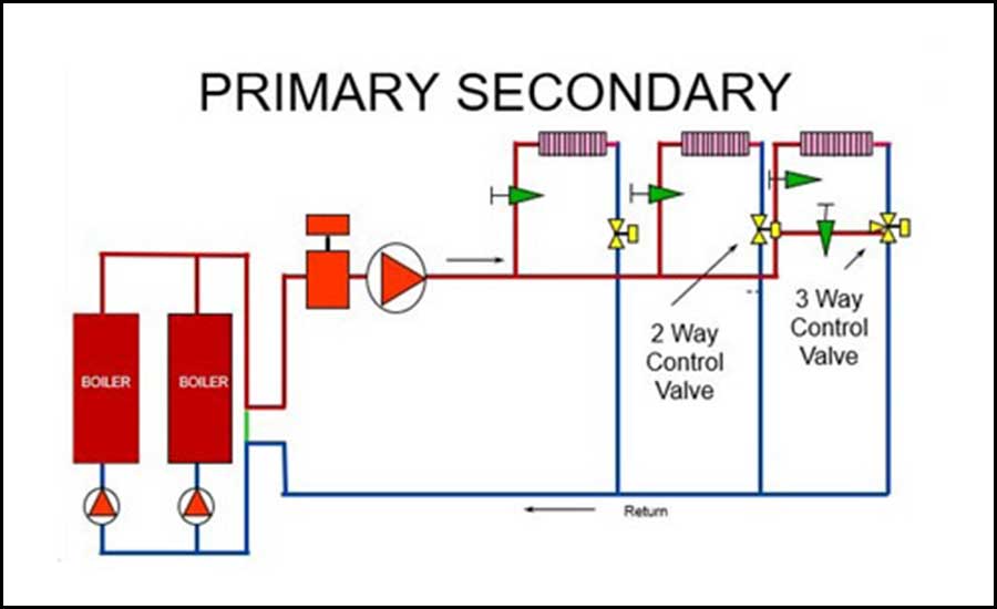
Primary-secondary piping arrangements include two sets of pumps: smaller primary pumps that circulate heated/chilled water to the main, larger secondary loop through common piping to ensure the flow and velocity required within the source equipment but does not interrupt the flow of the secondary loop.
The secondary system pumps, or circulators, supply fluid to terminal units (zones) to ensure the flow and velocity required through the distribution piping — also without interrupting flow of the primary loop.
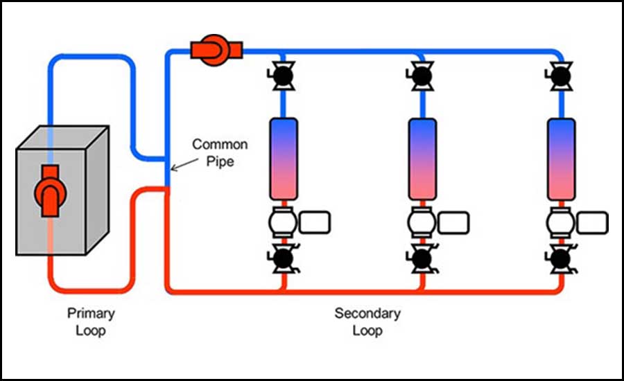
Primary-secondary piping systems require a primary pump for each boiler, and a larger system pump, along with the attendant need for their control, electrical use, and installation cost. System pumps distribute water to terminal units, and boiler pumps circulate water through a loop that separately serves the heating or cooling equipment. The two piping systems are hydraulically separated, or "decoupled." Typically, primary-secondary piping arrangements dictate full flow in the boiler loop and variable flow in the system loop.
With primary-secondary arrangements, a common pipe allows flow to change in one system without affecting flow in the other system. So, flow rate may be different through the boilers and the secondary system.
Primary-secondary piping accomplishes three levels of performance and protection. It saves boilers from the torture of minimum flow (with two-way valves standing guard to prevent). The arrangement also guards against return delta Ts (∆T) greater than 30° or 40°F. And, boiler controls typically can’t adjust firing rate fast enough to match system demand.
One of the key purposes of primary-secondary piping is the protection of one zone from changes of flow in another.
"Chillers, like some boilers, can’t manage extremely low flow rates that are throttled way down. Primary-secondary piping offers needed protection because it allows a primary pump to operate at the flow rate required by a boiler or chiller regardless of the what the distribution side’s requisite flow rate is,” said Jim Schnorr,” vice president of business development, for manufacturer’s rep firm, N. H. Yates.
“The primary loop may employ a variable-speed primary pump, allowing the flow rate through the source equipment to ramp up and down with firing rate to maintain desired delta T and operate boilers within manufacturers parameters” continued Schnorr.
One way of looking at what defines a primary-secondary piping arrangement is that design engineers adapt system piping to accommodate boiler or chiller limitations.
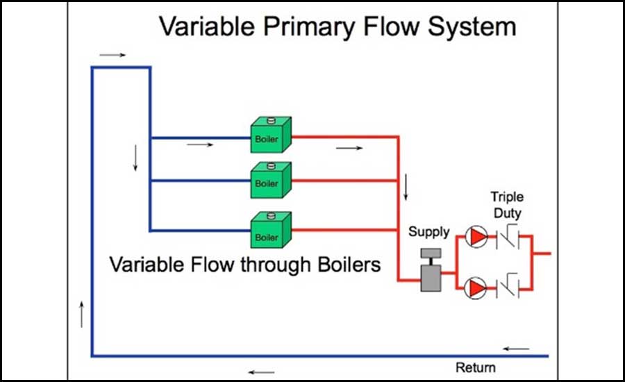
An alternative to primary-secondary piping, variable primary, allows design engineers to select system design requirements, and a boiler and/or chiller to match the specified design. And, unlike the primary-secondary arrangement, a boiler is integrated into — not separated hydraulically from — the system loop.
Variable primary systems offer the same flow rate through boilers and the piped system. In such arrangements, the boiler and/or chiller, valve, and piping pressure drop is added to the main system pumps — and this must be accounted for and overcome, yet the overall pumping energy is typically less than what’s required for a primary-secondary system.
For optimal system performance, variable primary systems need on-off automatic or motorized butterfly valves at each boiler; this eliminates inefficient water flow through inactive boilers.
Variable primary systems have a minimum flow rate required for the system pump(s). The system will require some means, by way of three-way control valves, for instance, to protect the pump from operation below the pump’s minimum flow rate (engineers can check that flow rate against the minimum boiler flow rate).
In variable primary piping systems, one set of system pumps is usually piped in parallel to circulate water through the heating equipment and distribution piping to terminal units.
This arrangement can result in lower initial costs due to the installation of fewer pumps, and requires less piping and less electrical work. Variable primary systems are widely considered to be more energy efficient, too — fewer pumps use less energy. Proponents also point out that it serves to protect the most valuable system component: the boiler. However system flow is set from the distribution system, and boiler minimum and maximum flows must be accounted for in pump programming.
Variable primary piping systems became popular with the advent of condensing boilers (typically offering turndown ratios of 5:1, 10:1, or up to 20:1), with a variable system flow where the pump is used to accomplish precise “load match” capability while reducing the owner’s need for electrical usage. This piping design uses only the system pump to flow water through the system and boilers. Of note, often the system pump is too large to turn down to minimum boiler flows; pumps typically can’t flow below 50% of maximum capacity. This has prompted some engineers to utilize two smaller system or secondary pumps, but this adds cost and complexity. Thus the need for the alteration in piping, leading to the variable-variable system design.
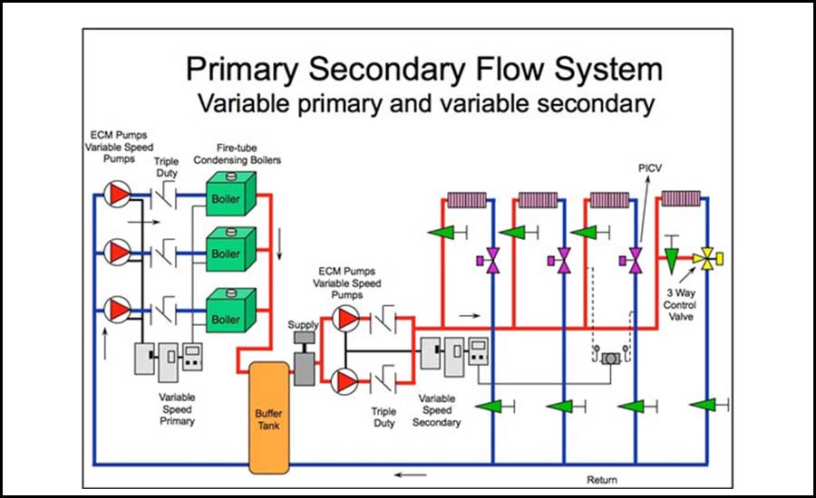
Variable-variable piping takes the best of both system piping designs by combining the primary-secondary concept (protecting the boilers) by coupling it with the variable-primary design (utilizing variable flow). This is accomplished by using a variable-speed pumping solution not only on the system side but also on the boiler side, adding additional savings with fuel usage.
One key factor has allowed this to happen with the greatest of ease. Modern ECM pumps, or permanent magnet pumps — paired with variable-frequency drives — are capable of providing very precise circulation by throttling up or down and ramping up or down to match demand.
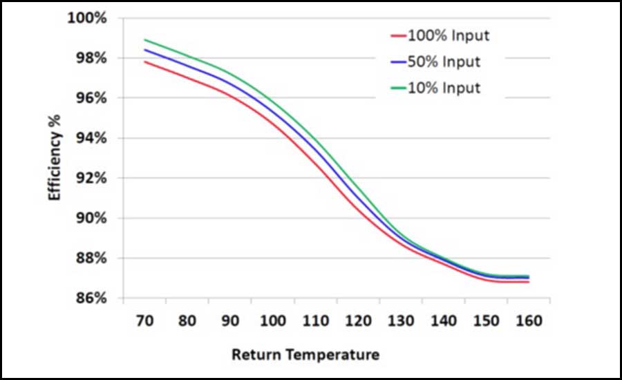
For contemporary modulating-condensing boilers, abundant condensation — which facilitates optimal, high-efficiency operation — occurs in the heat exchanger when the return water temperature back to the boiler drops below 130°. The lower the return temperature, the higher the temperature differential (∆T) between supply and return, the more condensing takes place, the better the efficiency. Flow rate also contributes to higher efficiency gains by up to 1% to 2% (see Figure 5 for a typical condensing boiler efficiency curve).
To maximize the amount of time a boiler condenses, flow rate through the heat exchanger and the boiler’s firing rate should modulate.
“Traditional operation called for a fixed-speed circulator sized to provide the correct flow rate and desired delta T at [hydronic boiler] high-fire only,” said Schnorr. "We know a typical modulating boiler fires just 15% of the time in high fire. But this makes it impossible to provide ideal flow at lower burner inputs that occur during a majority of every call for heat.”
Schnorr added that hydronic systems can benefit from variable-speed technology 51 minutes out of every hour of firing.
“To clarify, the load demand fluctuates during any given hour of the heating period, essentially 51 minutes within each hour, with a constant/fixed speed full-flow pump," he said. "So, by not using variable-speed pumping, the consumer is 'overpumping' or wasting electricity.”
In essence, many hydronic systems are over-pumping. Three-quarters of the time, operation is optimal. But that still leaves plenty of room for improvement. When it comes to over-pumping, the end user is spending more money unnecessarily to operate a pump at full flow, and if it’s a condensing boiler, then they would also be losing up to 2% in fuel savings.
With 15% of a commercial modulating/condensing boiler’s runtime at high-fire, that means the unit coasts along at medium- or low-fire 85% of the time. This is the “sweet spot” that produces maximum condensation and highest system efficiency.
Explanation: Eco Propel Cognitive Pump Technology is a variable-speed control for Thermal Solutions Products’ line of Apex condensing boilers. This entails integration of boiler firing rate with pump speed to improve boiler and system efficiency while reducing electric and fuel consumption. A 0- to 10-v signal is communicated to a pump to ensure desired flow and ∆T are returned across all firing ranges.
Until recently, changing the flow rate through a light commercial boiler to match Btu input has largely been an afterthought. Just five or six years ago, only a few boiler manufacturers offered variable flow to optimize system efficiency as an option. The general consensus seemed to be it simply isn’t economical to pay for the upgraded variable-speed circulator.
The bigger picture: conserving gas
To a great extent, most references to the use of variable-speed circulators for boilers have focused on electrical efficiency. Based on the inherent efficiency of ECM motors and the ability to run at much lower speeds, electric consumption falls significantly — by as much as 85% to 90%. But in the grand scheme of things, only one circulator is involved.
“The real advantage is fuel savings,” Schnorr said. "Eight years ago, and with the cooperation of Taco, Thermal Solutions developed a variable-speed boiler pump kit called Eco-Propel. The modification they made was simple, and it consistently yielded up to a 3% reduction in gas consumption.
This was accomplished by increasing heat transfer at low- and mid-fire rates where over-pumping limits condensing performance. And, 3% might not sound like much, but when assigning a dollar value to the gas that an 825 MBH boiler uses over the course of a year — or several for that matter — the savings accumulate quickly. This is the catalyst for using variable-speed pump technology coupled with condensing boilers.
Schorr pointed out that, while testing the Eco-Propel kit, they consistently found a 6° to 10° reduction in return water temperatures over the course of a firing cycle. Each degree is critical in producing as much condensate as possible. More heat stays in the system, while less goes out the stack.
Ultimately, the result was an all-inclusive, plug-and-play boiler pump package that provides a 12-month payback in the Northeast based on heating degree days and fuel prices. A user’s ROI varies, chiefly dependent on what part of the country the boiler’s located in, but is typically in about two years’ time.
Circulator adaptation
According to Schnorr, Thermal Solutions began to work with Taco experts to select and modify an ECM circulator for the task.
Taco’s engineering department examined the pump requirements and found their ECM-powered VR15 offered the correct performance curves.
The only hurdle was the pump’s ability to receive a 0- to 10-v signal. Taco pumps had that capability for several years, but had not yet implemented it on the 00e line of high-efficiency circulators because the demand didn’t justify it. This was the same challenge Thermal Solutions was finding with other pumps available in the same category.
At the very beginning of the project, engineers from both firms attempted to run the variable-speed pump with a set of temperature sensors on the supply and return pipes. While the sensors work well within a distribution system, there was a slight lag time that they weren’t willing to tolerate for the application. And, there was the possibility of firing rate and pump flow fighting each other.
The solution was to orchestrate all facets of operation — optimizing boiler modulation and system flow — through the Apex boiler’s control.
Savings trifecta
“There are actually three ways that this solution conserves resources,” Schnorr said. “Annual electrical and gas savings are easy to quantify; $245 and $600, respectively ($245 savings in electrical cost and $600 in fuel costs versus constant/fixed speed full flow pumping practice ) in the Northeast. The last benefit, boiler longevity, is just as real but more difficult to quantify.”
By reducing the number of boiler cycles and limiting thermal shock to the heat exchanger, the use of a variable-speed boiler circulator extends the service life of the condensing boiler. In addition to boiler longevity, circulator life also is extended. This is due to slower motor operation during the vast majority of runtime hours.
Electrical consumption is also reduced by the water-tube heat exchanger. Its design permits low flow rates and high delta Ts, finely tuning system efficiency, Schnorr stated.
The future is now
The industry is moving from fixed-speed/variable-speed systems (boiler loop/distribution) to variable-variable-speed. This especially is true on commercial projects. Over the past several years, engineers and installers in the U.S. and Canada have grown comfortable with variable-speed distribution and its benefits. But as buildings become more efficient, flow rates are reduced and supply temperatures fall, there’s a real need for the boiler to respond accordingly.
“This is definitely what the hydronic industry needs to maintain its competitive advantage,” Schnorr said. “And in many places, variable-speed boiler pumps and circulators are incentivized. I believe this is really an evolution in system piping to maximize system efficiency and eliminate wasteful over-pumping. The technology is here; the question is, will we embrace it in new designs and the replacement market.”


