
Geothermal heat exchangers almost always use condenser water or glycol as the heat transfer medium — and, sometimes, refrigerant. Wastewater heat recovery systems typically preheat domestic cold water directly or use a refrigerant as a heat extraction medium. Solar thermal systems preheat domestic hot water by means of a drain back system or glycol medium. Heat recovery air-handling systems use heat wheels, plate heat exchangers, heat pipes, or runaround coils to exchange heat or cooling from the exhaust air to the supply air.
Heat recovery chillers can simultaneously generate 130°F heating hot water and 42° chilled water, but water-cooled chillers have to have these loads balanced, which sometimes but rarely occurs in most buildings. Six-pipe water-cooled chillers use a geothermal heat exchanger in the ground as a source or sink to balance the loads. Four-pipe air-cooled heat recovery chillers use the condenser coil as a source or sink with the ambient air.
Rethinking heat recovery
What if heating hot water or chilled water was sent into a geothermal heat exchanger instead of condenser water? We would have a higher water temperature of 130° to reject heat to the ground rather than a typical 90° condenser water temperature. Chilled water at 42° to 45° would extract heat from the ground rather than 32° glycol or 36° to 45° condenser water.
Wastewater heat recovery systems can use chilled water to extract heat rather than a DX refrigerant system, and heating hot water can be used to reject heat to wastewater rather than refrigerant. Using wastewater as a heat source and particularly as a heat sink are very under-utilized opportunities currently. Raising wastewater temperature helps the anaerobic bio-degradation process and 50% to 60% of the operating cost of a wastewater treatment plant is to enable sludge de-watering1, 2. The optimum temperature range for waste water biodegradation is 72° to 113°1.
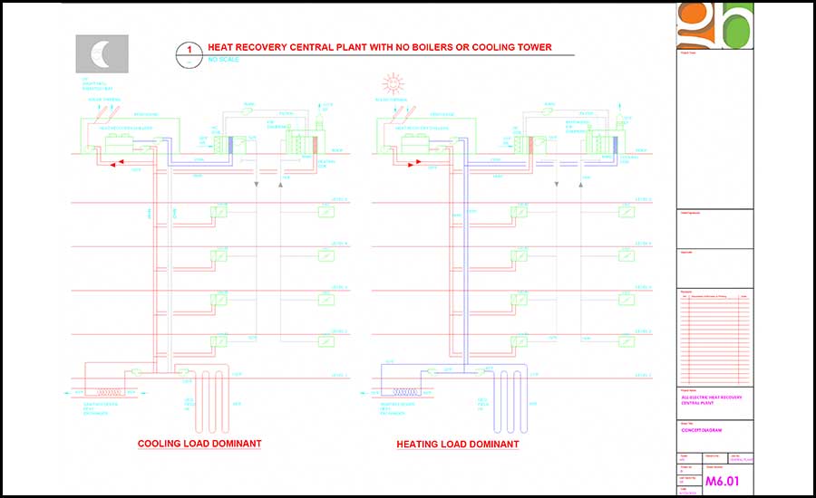
How about sending chilled water to a solar thermal system to pick up heat? Or sending heating hot water up there when it is dark for night radiant cooling?
Now, for the most cost-effective opportunity. In the exhaust air stream after, for example, a runaround coil, what if we have a chilled water coil to extract every last bit of heat from the exhaust air? Or we have a direct evaporative medium upstream of a coil we are running heating hot water through to reject the maximum amount of heat from the building. These sources and sinks of heat are much more efficient than an air-cooled chiller and very first cost-effective.
A source/sink exhaust coil with evaporative pre-cooling
Let’s consider an outdoor design temperature over 110° (becoming much more common these days). A typical air-cooled chiller or heat recovery chiller (HRC) will use 110° air to reject heat from the condenser with a likely efficiency of 1.6 kW/ton and 7.4 EER, or worse. In winter, the HRC might be trying to pull heat from 30° ambient air or lower, when its COP might be only 1.9 or less.
In a typical project the exhaust air temperature after the exhaust fan heat pick up is 81.5°, and the direct evaporative cooler lowers that to 64.2°. With 113.5° outdoor air on the supply side of the plate heat exchangers, the 64.2° exhaust air temperature is raised to 92.9° and, on the supply side, the outside air temperature is reduced to 84.8°. The 130° heating hot water then rejects heat to that 64.2° exhaust air, raising its temperature to 124°. The water-source heat recovery chiller (simultaneously producing 42° chilled water and 130° heating hot water) has a peak efficiency of 1.28 kW/ton, NPLV of 0.72 kW/ton, EER of 9.4 and a COP of 6.52. This is significantly more efficient than an air-cooled chiller and also reduces equipment space requirements and ambient noise.
It should be noted that in winter conditions with an outdoor design temperature of 31°, a plate heat exchanger, heat pipe, or runaround coil can recover enough heat from 72° exhaust air to provide 55° supply air with no pre-heating coil. The exhaust air is 48° at this point, and 42° chilled water can further extract 6 btu/cfm with a discharge air temperature of 42.4°.
Load balancing with a source/sink exhaust coil
If a geothermal heat exchanger or thermal storage are not included in the design, depending on the hours of operation of the facility and the 24/7 loads in the building, consideration may need to be given to adding an electric resistance boiler for cold starts. This boiler should be placed on the chilled water system so that the heat recovery chiller can raise the COP from 1 to 6 or so.
In a VAV tracking system, the amount of heat that can be extracted from the exhaust air stream is limited by the exhaust cfm, which is in turn dictated by the supply cfm for balanced pressure in the building. In order to increase the available heat source, a bypass on the rooftop exhaust duct can be added which brings in more outside air for heat recovery, just like an air-cooled chiller. This only helps when the chilled water temperature is lower than the outside air temperature, so below 42° to 45°it does not work and other means are required.
Buffer tanks on the chilled water and heating hot water side of the heat recovery chiller are typically required to prevent compressor cycling. These are often sized at 6-10 gallons per ton, but can be made larger to enable cold morning starts without the need for an electric boiler. Increased chilled water storage may also be used for arbitrage cost savings.
Applications and suitable project types
Using 100% outside air for heat recovery and load balancing with 4-pipe water-source heat recovery chillers certainly makes sense for labs, health care and other projects requiring high outside air percentages and 24/7 operation. However, there is no reason why office buildings and other lower outside air or intermittent occupancy projects cannot employ this technique to provide improved indoor air quality and airborne infection control with a more energy efficient design than an air-cooled heat recovery chiller approach.
This design can be used to retrofit existing buildings that use chillers, cooling towers, gas boilers and air-handling units (including economizer AHU’s) so that they become all-electric and carbon free. For sure it makes even more sense if a major renovation is being considered and the existing equipment has reached the end of its useful life.
The space used for boilers and cooling towers can be reclaimed for other uses, and the natural gas building connection eliminated. Water usage will be significantly reduced as evaporative cooling uses a small fraction of the water that a cooling tower uses. Note direct evaporative cooling of the exhaust air is only engaged when the outside air temperature is above 60F.
Existing return and exhaust ducts and shafts may not need to be reconfigured, but just combined at the roof to eliminate existing return and exhaust fans and increase heat recovery potential. When retrofitting air handling systems, increased resiliency can always be had by using a fan-wall system on the supply and exhaust with a redundant fan in each array.
This all-electric heat recovery approach can be used anywhere in the world and on most building types, and is especially effective where high ambient temperatures are becoming more prevalent, or where low ambient temperatures occur.
Some project types where an all-air 100% exhaust approach needs to be evaluated include museums where close humidity control is required and 100% outside air is not desirable. Also, existing buildings with very low floor to floor heights might also make an all-air system challenging, but then radiant or fan-coil solutions could be employed.
These issues would not preclude the use of geothermal, waste water, thermal storage or solar thermal with water-source heat recovery chillers in place of 100% exhaust air heat recovery for load balancing. And of course we can always use 4-pipe air-cooled heat recovery chillers alone or in conjunction with these more efficient mechanisms.
Existing building upgrades
Electrification of existing buildings may or may not require an upgrade of the electrical service size. If an existing building is only mechanically ventilated and heated by gas, adding heat pump heating and cooling will certainly significantly increase electrical loads.
More often than not, however, no upgrade will be required because of the increased overall efficiency of the retrofitted heat recovery systems with lower outside air and fan motor loads. Often LED lights with daylight and occupancy controls are added to lower lighting loads. Improved computer efficiencies and switched outlets also reduce plug loads. Grid optimal designs that can shed lower priority loads may also be employed to avoid an electrical upgrade.
Theory or reality?
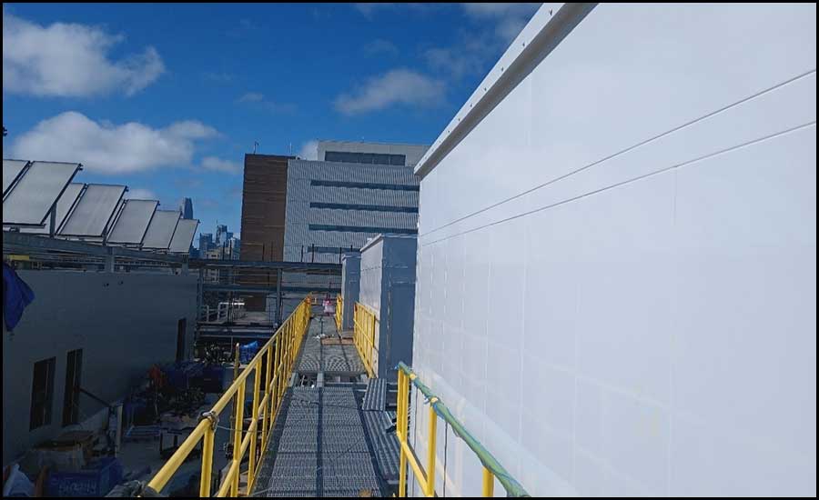
You may be thinking that this all sounds good in theory, but will it work in practice? The firm has two completed projects and two projects in construction that use this approach.
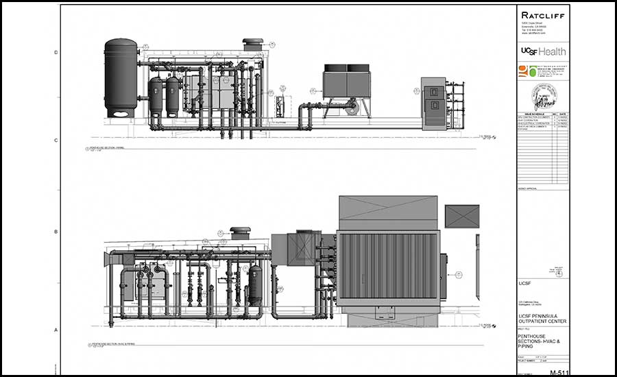
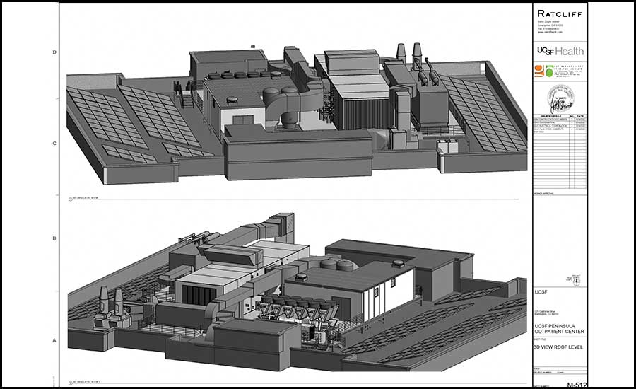
UCSF Mission Bay Block 34 OSHPD-3 ASC (Scheduled for Completion in April 2024) — A 190,000-square-foot, five-story, $230 million ambulatory surgery center with 16 operating rooms, recovery, compounding pharmacy, central sterile. All-electric, no natural gas. Two interconnected, 28,000 cfm, three-tier, 100% outside air heat recovery AHU’s serving Level 1. Two interconnected 28,000/40,000 cfm, 3 tier, 100% outside air heat recovery AHU’s serving Level 2. Two interconnected 54,000 cfm, three-tier, 100% outside air heat recovery AHU’s serving Levels 3-5. Each AHU has run around coils and six to 12 fans with one redundant. Four 300-ton screw heat recovery chillers, three required for the load, one redundant. Wastewater heat recovery, pre-heating DHW, and 45 solar thermal panels providing heat for DHW and HHW. Operates 24/7/365. LEED Gold targeted. Projected EUI 70 kbtu/square foot/year.
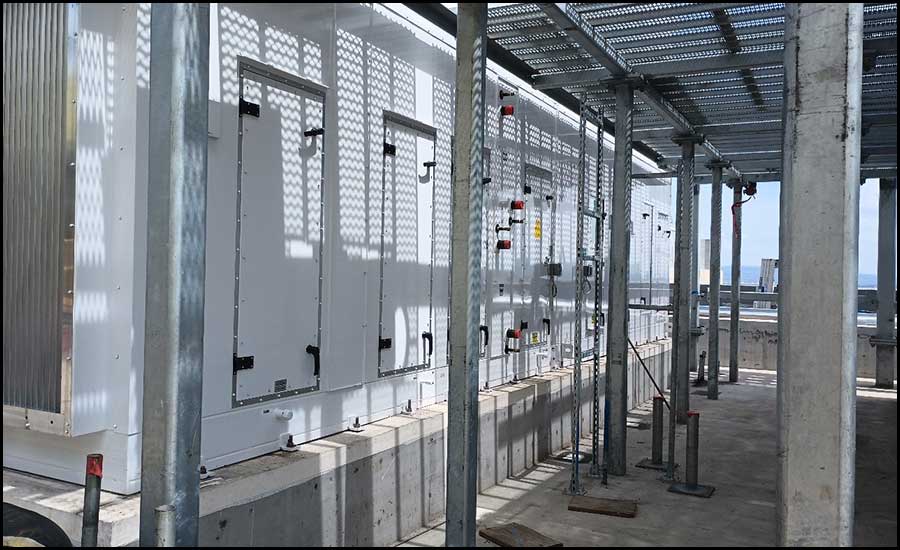
UCSF Burlingame Peninsula Outpatient Center and OSHPD-3 ASC (Scheduled for Completion in November 2024) —A 50,000-square-foot, four-story, $100 million ambulatory surgery center with four operating rooms, recovery, compounding pharmacy, central sterile, two MRI’s, CT, PET CT. All-electric, no natural gas. One 65,000 cfm, 100% outside air heat recovery AHU serving Levels 2-4. One 6,500 cfm, 100% outside air AHU serving pharmacy. Each AHU has two to 12 fans with one redundant. Three 68-ton modular scroll heat recovery chillers, two required for the load, one redundant. One 200-ton air-cooled magnetic-bearing centrifugal chiller. HHW from heat recovery pre-heating DHW. Vacuum drainage system. 40-kW PV system. Operates 24/7/365. LEED Gold targeted. Projected EUI 81 kbtu/square foot/year.
Footnote: A utility patent for this concept was applied for in early 2020 and was awarded Patent #11767987 by the USPO in September 2023.
References:
- Waste Management and Research: The Journal of International Solid Wastes and Public Cleansing Association (ISWA), Volume 34, March 2016, Pages 265-274
- Journal of Cleaner Production, Volume 214, March 2019, Pages 873-880


