
The commissioning of plumbing systems is not in every project’s scope, but when it is, the domestic hot water (DHW) system is often the first system included. Typically, the DHW system includes recirculation piping and an associated pump to ensure the water being recirculated throughout the building is of adequate temperature and is available at served fixtures relatively quickly. The commissioning effort for DHW systems will naturally focus on the installation and operation of the water heater and recirculation pump. However, some recent projects have taught me that I also need to watch for the inability to isolate individual DHW risers.
The issue
In recent years, I’ve been involved in many high-rise residential buildings. My involvement has never been new construction commissioning. In our locale, the project delivery process for these types of buildings almost always “value engineers” out such services. More effort and money are spent on making those new condos look pretty than on making the building systems function correctly. As such, we usually are called in a few years later for retro-commissioning services when building operations are not quite panning out. One of the common systems we find ourselves troubleshooting is the DHW recirculating system.
Inevitably, there will come a time when owners of individual units need to repair or replace fixtures. Unfortunately, the fixtures that were initially installed often did not include local isolation valves. I suppose such valves were value engineered out of initial construction as well. Thus, when work on a fixture is needed, the serving risers have to be drained as well. This adds time, cost, and a coordination hassle for what should be a relatively simple repair localized to an individual unit.
Riser drain downs for in-unit repairs are certainly unfortunate. Sometimes they are unavoidable for more expansive projects, like a full kitchen or bathroom remodel, which may require riser drain downs even if isolation valves were present at the existing fixtures. What really makes such drain downs painful is when you can’t isolate the serving risers. Poor piping layouts, coupled by crossover at fixtures, can result in many more risers needing to be drained than originally planned for.
The root cause
How exactly buildings find themselves in this precarious situation is a bit nuanced. It’s best explained by walking through a couple of different piping layouts.
Figure 1 shows an abbreviated domestic water piping schematic. Each riser (R-#), which may include both domestic cold water (DCW) and DHW pipes in it, serves fixtures stacked on top of each other.
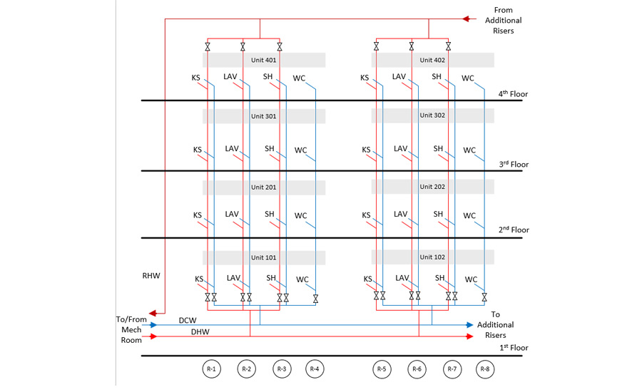
Often, the floorplan is identical from floor to floor, which allows for all the water closets to be served by a common riser, all the kitchen sinks to be served by a separate common riser, etc. If Unit 101 needs work done at the kitchen sink, ideally local isolation valves are located at the fixture. Unfortunately, they’re often not present, do not hold, or are not sufficient for the nature of the work being performed (e.g., moving the faucet from the counter to the island). If local isolation valves cannot be used for isolation, then the next logical step would be to drain the DCW and DHW pipes in riser R-1. Closing of DCW and DHW isolation valves at the bottom of the riser, as well as the DWH isolation valve at the top (to prevent back-feeding from recirculated hot water [RHW piping), would effectively isolate the riser. This will result in a water outage only for the kitchens in the -01 units.
Unfortunately, isolating riser R-1 in the example above may require entrance into Unit 401 to find the isolation valve at the top of the DHW riser. For this reason, as well as to save on the cost of valves, riser isolation valves are often located in common areas (e.g., first floor hallway, fourth floor hallway). Additionally, the installing contractor usually groups multiple risers (ideally serving a common stack of units) off the same valve, see Figure 2.
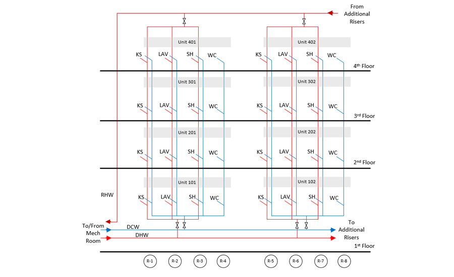
With this approach, work at Unit 101’s kitchen sink will require the isolation valves at the bottom of the risers that serve the -01 units on first floor and the isolation valve at the top of the risers serving -01 units on fourth floor to be closed. Now, all fixtures (kitchen sink, lavatory, shower, water closet) in the -01 units will have a water outage during a Unit 101 kitchen remodel.
The layout in Figure 2 certainly increases the impact the work at Unit 101’s kitchen sink will have when compared to the layout in Figure 1. Sadly, the impact is even more widespread. What you often see, in both the design and installation of these systems, is a mismatch between the grouping of DHW risers served by the isolation valves on the supply (e.g., first floor) and the grouping of DHW risers served by the isolation valves on the recirculation piping (e.g., fourth floor). Figure 3 is a good example of this situation.
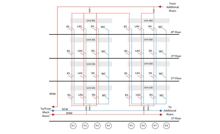
If the building exhibited the piping layout in Figure 3, and Unit 101 was pursuing the kitchen remodel, then closing isolation valves outside Units 101 and 401 would not be sufficient. DHW would back feed into the risers serving the -01 units via the DHW pipe at the top of riser R-5, as R-5 inappropriately got grouped into the set of risers served by the isolation valve outside of Unit 401. Now all the risers that R-5 is grouped with from the bottom (R-6, R-7, and R-8) also need to be isolated, so the DHW isolation valve outside of Unit 102 and outside of Unit 402 will also need to be closed. Now, Unit 101’s work is creating an outage for all fixtures in eight units.
One might think this means that the -02 units could still get DCW service. Theoretically, yes. Unfortunately, that is not usually the case. Most often, the DCW needs to be drained as well. The reason being that it’s likely one of its served fixtures on R-7 serving showers may have a mixing valve that has failed and is susceptible to crossover1. Crossover occurs when internal components of a mixing valve — typically for showers and baths — fail, and a pressure differential between the serving DHW and DCW pipes drive water from one piping system into the other. Such crossover is widespread in high-rise condominiums. In one building I work in, the homeowners association had so many instances of crossover due to failed shower and bath mixing valves, that it proactively replaced all such fixtures in the building — a total of over 600 such fixtures.
The prevalence of this mistake
The insufficient piping/valving arrangement shown in Figure 3 may seem like an isolated incident. However, I have firsthand experience with three buildings subjected to this issue. Each of those buildings had a different designer and a different plumbing contractor during initial construction, so this issue cannot be attributed to one ignorant player in the industry either. From my experience in those three buildings, the areas where a mismatch between the DHW risers grouped onto a single supply pipe’s isolation valve and the DHW risers grouped onto a single recirculation pipe’s isolation valve was most likely to occur when the floorplan was changed.
The fix
If your local market has similar trends to mine, then you probably won’t be commissioning such high-rise residential buildings at their inception. However, the issue described in this article could be present in any type of multistory building. The ramifications of it are just exacerbated in high-rise residential buildings where the number of plumber risers are much higher and there are so many more stakeholders to coordinate amongst.
The following principles apply to both new and existing building commission services and can help guide you in providing value to your clients:
- Fight for isolation valves — The great plumbing engineer Alfred Steele said, “Being overly frugal in the installation of valves is often false economy.”2
- Appropriately group risers — Identify where there are mismatches between the DHW risers grouped onto a single supply pipe’s isolation valve and the DHW risers grouped onto a single recirculation pipe’s isolation valve.
- Develop a facility standard on mixing valves to minimize crossover — There are some make/models out there that are notorious for failing. One facility I work in now requires auxiliary check valves to be installed on DHW and DCW branch lines serving each fixture, which has a mixing-style valve.
- Include vent and drains at the top of risers in common areas — This will prevent having to drain the riser at fixtures within the lowest-level unit and having to vent the risers at fixtures within the highest-level unit. This may not always be possible.
- Don’t allow for isolation valves on the recirculation side of a riser to also be used as a balancing valve — This throttling of the isolation valve promotes scale accumulation, which will eventually prevent the valve from being able to be completely closed. See Photo 1 below of just how bad it can get.
- Exercise riser isolation valves regulatory — I once had a facilities engineer giving a tour to some students of mine at the Air Force Institute of Technology. As he spoke to the students, he was constantly exercising isolation valves on the various HVAC and plumbing systems we were walking past. He didn’t even realize he was doing it. When questioned by students, he mentioned he rarely has an isolation valve hold when he needs it to, and he has made a commitment to never pass up an opportunity to exercise a valve. I found that concept profound, and it has stuck with me ever since.
Conclusion
Making sense of this poor piping practice and the nightmare it creates for homeowners’ associations was a hard lesson learned for me. I didn’t have clean schematics like Figures 1, 2, and 3. I didn’t even have anything close to accurate as-builts. It took many hours of coordinating access into individual residence, tracing piping, and running outage tests to effectively map the domestic water distribution systems. Only then could I step back and analyze what was going wrong. I hope this article consolidates the lessons I learned through the process to better equip readers to identify and rectify similar issues in the future.
References:
- Ayala, G. Zobrist, D. 2016. “Testing For and Determining the Prevalence of Crossover in a Multifamily Central Domestic Hot Water Distribution System.” ACEEE Summer Study on Energy Efficiency in Buildings.
- Steele, A. 2006. “Engineered Plumbing Design II.” American Society of Plumbing Engineers


