
A refrigerant transition is underway in the HVACR industry, which is affecting how HVACR service technicians install and maintain commercial refrigeration equipment. As the phasedown of hydrofluorocarbon (HFC) refrigerants ramps up over the next several years, technicians can expect to see a wider variety of refrigeration architectures that use lower-global warming potential (GWP) alternatives.
Compared to legacy HFCs, these emerging refrigerant substitutes have unique properties and characteristics that impact system design and servicing considerations. To navigate this evolving landscape, service technicians should educate themselves on the fundamentals of working with the next generation of lower-GWP refrigerants.
But despite critical differences and refrigerant-specific nuances, most long-held and widely adopted servicing best practices still apply.
Working with the next generation of lower-GWP refrigerants will require familiarity with already approved substitutes — namely, CO2 (R-744) and R-290 (propane) — and a new class of A2L alternatives. CO2 is gaining popularity in transcritical booster systems throughout North America, especially as integrated controls and components have advanced significantly to manage its high pressures and simplify servicing.
Classified as a higher-flammability A3 refrigerant, R-290 has been used in small-charge (i.e., 150-gram), stand-alone and factory-charged refrigerant systems for more than a decade. If approved, recent proposals by the Environmental Protection Agency’s (EPA) Significant New Alternatives Policy (SNAP) Rule 26 would increase the capacity of these systems, with charge limits up to 500 grams in some end uses.
SNAP Rule 26 also proposes the introduction of lower-flammability A2L refrigerants in stand-alone and remote commercial refrigeration equipment, per use conditions. The new, sector-based refrigerant proposals are founded on the safe product design and application principles mandated in the Underwriters Laboratories (UL) 60335-2-89, 2nd edition. Technicians can work confidently knowing that A2L- and R-290-qualified systems are safe when designed with requisite risk management and safety mitigation strategies, as needed.
As each refrigerant is poised to play unique and specific roles within commercial refrigeration, it’s important to understand their respective potential impacts on system servicing and adhere to the UL 60335-2-89, 2nd edition requirements, if applicable.
Expanded potential for R-290
In most stand-alone equipment, R-290 systems are critically charged and hermetically sealed at the manufacturer’s facility. Malfunctioning units are typically refurbished by a qualified technician and/or reconditioning company. If servicing is required, it’s important to follow R-290 servicing procedures.
Before entering a service area, use a portable gas monitor that can alert you to the presence of R-290 in the air. Always wear the required personal protective equipment (PPE) to ensure safety. Brazing should be performed only by qualified personnel and under specific precautionary conditions. Check all brazing and silver soldering equipment for leaks and proper pressure settings.
Refrigerant must first be evacuated with a vacuum pump and purged from system lines with an inert gas (e.g., nitrogen). Before working on a stand-alone, R-290 system, it should be moved to an unconfined, unoccupied and well-ventilated area. If possible, place a fan in the room to ensure active ventilation.
Understanding A2L systems and safety standards
Lower-flammability A2Ls are well on the path to regulatory approval and poised to fill expanded roles across a broad spectrum of commercial refrigeration systems, including:
- Stand-alone equipment
- Remote, outdoor condensing units
- Distributed systems
From both servicing and safety perspectives, A2Ls introduce terms and concepts which are based on the UL 60335-2-89, 2nd edition safety standard. In addition, technicians will need to become familiar with how the standard determines allowable charge limits and mandates safety mitigation measures.
Lower-flammability limit (LFL) — Each A2L refrigerant has a unique LFL rating, which is then used to calculate charge limits. For example: the LFL of R-454C is 0.293 grams per cubic meter (g/m3). LFL is based on the worst-case formulation (WCF), as defined in ASHRAE 34.
A2L charge limits — The UL 60335-2-89, 2nd edition safety standard delineates system charge in three categories of increasingly higher limits:
- m1: smaller-charge, stand-alone refrigeration units, typically with a few pounds of refrigerant. These would be very similar to stand-alone, R-290 units, only the large A2L charges would enable higher-capacity systems.
- m2: remote condensing units (e.g., for large walk-in coolers and freezers), typically charged with 10–30 pounds of an A2L refrigerant
- m3: larger remote, parallel rack systems, typically charged with more than 100 pounds of an A2L refrigerant
For an example on relative system charge sizes, the A2L refrigerant R-454C (148 GWP) would have the following maximum limits:
- m1 charge limit = 8 pounds
- m2 charge limit = 33 pounds
- m3 charge limit = 166 pounds
Risk mitigation — Due to the higher A2L refrigerant charges on m2 and m3 systems, safety mitigation measures and installment room characteristics must also be considered, including:
- Leak detection — Considered a best practice in A1 HFC systems, leak detection sensors and/or devices are now required for m2 and m3 systems. They should be installed near case evaporators, enclosed/occupied walk-ins and at the condensing unit.
- Room area — The room area of the refrigerated and/or occupied space (e.g., walk-in cooler) is a key consideration of safety mitigation. Air ventilation and circulation are among the safety mitigation measures that may be required.
- Releasable charge — This refers to the portion of the system refrigerant charge that can be released into a refrigerated and/or occupied space upon detection of a leak.
- Safety shut-off valves (SSOVs) — Also referred to as isolation (ISO) valves, SSOVs are installed on both the liquid and suction lines outside the refrigerated case to regulate the amount of releasable charge. SSOVs are configured and/or connected to the leak detector/sensor and/or case controller to trigger shut-off at 25 percent of the refrigerant’s LFL — at which point, the system will automatically shut down to ensure safety. For early detection and additional safety, leak detection alerts can be triggered upon detection of 5 percent of LFL.
A2L servicing best practices
Because each A2L refrigerant has a unique LFL rating, the first step in A2L servicing best practices is to identify which A2L refrigerant is being used. Look for refrigerant labels on the system and red markings on all service fittings; and clearly mark fittings for future servicing. Use only A2L-certified gauges, vacuum pumps, and leak detection and refrigerant recovery machines.
Servicing A2Ls requires three steps that are already considered industry-accepted best practices: evacuate, purge and test for leaks. If possible, try to work in a well-ventilated area and deploy a continuous leak monitoring and detection system.
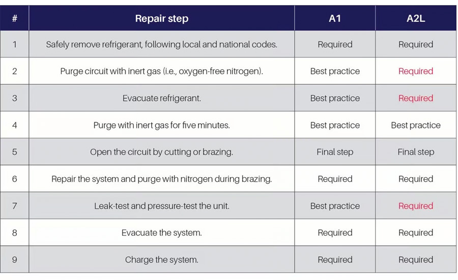
Braze all connections before embarking on higher-risk activities and be aware of your servicing space, including the presence of other people or potential hazards. For the most part, typical A1 system best practices are required on A2L systems.
Note: it’s important to use only A2L-qualified components and controls, and only charge systems according to their designed charge limits.
CO2 characteristics and considerations
Compared to traditional HFC-based systems, CO2 (R-744) has unique characteristics that introduce servicing considerations for technicians. Its high system pressures, low critical point and high triple point impact refrigerant storage, system charging and other key servicing requirements.
Proper storage of CO2 tanks can be a new area of concern for technicians and/or contractors unfamiliar with CO2 systems. Because CO2 tanks are designed to handle its high pressures, they weigh significantly more than standard HFC tanks — potentially up to nearly 200 lbs. A full charge of a 2,000-lb. system may require 40 cylinders weighing 8,000 lbs. (i.e., 4 tons).
Because of this weight consideration, technicians need to plan for storing the reserve refrigerant and be aware that storing high quantities of CO2 will affect building codes. For example, if it is stored on a retailer’s mezzanine, the structure must be capable of handling the total storage weight.
System charging is an especially important consideration with CO2 systems, primarily because liquid R-744 will turn to dry ice if a system is at the triple point pressure of 60.4 psig. To avoid this occurrence, technicians must charge with vapor until system pressures exceed the triple point pressure — typically beyond 100 lbs. psig — and then finish charging with liquid.
CO2’s coefficient of expansion (COE) is higher than a typical HFC refrigerant, which can cause pressure to rise rapidly when liquid refrigerant gets trapped in between two valves. Pressure can increase 145 psig for every 1.8 °F increase in temperature. Many systems are fitted with appropriate pressure-relief valves at the location of the trapped liquid to prevent pressure rise and assist with system servicing.
Leak detection is also an important consideration for maximizing the performance and safety of CO2 systems. R-744 is colorless, odorless, and heavier than air — and can be potentially toxic in high concentrations. Leak detectors should be mounted 18 inches off the ground and below the breathing level. Early detection can prevent CO2 system performance issues and protect food quality.


