
As our industry continues to adopt more advanced building information modeling (BIM) techniques, and more data is becoming available that can be automatically read, compared, and manipulated. Software can now determine space type, loads, and adjacencies directly from an architect’s model. This technological shift allows zoning to be automatically determined for a given model. Unfortunately, the preeminent source for HVAC design, “The ASHRAE Fundamentals Handbook.” has this to say about zoning: “… a truly automated, one-size-fits-all approach remains to be developed.”
This article will focus on multi-zone variable airflow volume with reheat (VAV) systems. In this system, a central air moving unit — commonly referred to as an air handling unit (AHU) or rooftop unit (RTU) — returns air from multiple spaces, mixes it with outdoor air, filters it, then heats or cools as necessary to provide air to a VAV unit. That unit then modulates the flow of air to the spaces and reheats it as necessary to meet a space temperature set point.
VAV systems are the most economical and efficient systems for most buildings4. Additionally, the International Energy Code and ASHRAE 90.1 require any space over 4.5 tons and any building over 40 tons to be provided with an air-side economizer5. This means that the ductwork must be provided to supply full cooling to a space, even if terminal units, such as fan coil units or heat pumps, handle the internal loads. Because the ductwork must be sized to provide full cooling from an outdoor air source regardless of the terminal unit type, the energy code makes other system types much less economically viable than VAV systems. Therefore, this article will focus on VAV systems, although the principles discussed may apply to different system types.
Spaces served by VAV reheat systems have two separate zone considerations: an AHU zone and a VAV zone.
AHU Zoning Economics
All spaces combined on a VAV must also be in the same AHU zone. Therefore, buildings must first be broken down into AHU zones before they can be broken down into VAV zones. Quality AHU zoning relies on a few principles: economics, space usage (specifically ASHRAE 62.1 pollutant groups), and building geometry.
There are four main concerns when it comes to AHU selection economics. First is that the larger the AHU, the less installation, maintenance, and energy costs. One 20,000-cfm AHU costs less than two 10,000-cfm AHUs and requires less labor to install. Additionally, less ongoing maintenance is required, and large fans are more efficient than small fans.
Second, the taller the building, the more the project will cost because of the taller columns and increased façade area. If the architect wants 9-foot ceilings and the MEP trades need three feet of plenum space, then approximately one quarter of the façade and column cost is the responsibility of the MEP design. HVAC zoning affects the way AHUs and shafts are distributed through the building, which may increase the required plenum space. An effort should be made to keep ducts in plenums as shallow as possible.
Third, energy, the slower the air moves through the AHU and duct, the less energy it uses. Therefore, larger ducts and AHUs are more efficient, but that must be balanced with the points above. Thankfully, the international energy code section C403.8.1 guides the engineer with an allowable fan horsepower5. Depending on the duct pressure drop, the AHU can increase in size to reduce the total fan pressure drop and meet the allowable fan horsepower.
Finally, shafts and mechanical rooms cost floor space, which means they cost money. To any building owner, usable area is equivalent to money. Taking away an office or dwelling unit and replacing it with a mechanical room might cost the owner more over the life of the building than the entire AHU. Shafts and ductwork are frequently used to allow the large AHUs to be shifted to less desirable areas of the building that can’t be used anyway, such as rooftops, basements, or interstitial floors that correspond with structural requirements. While this is great for building use, it is important to note that mechanical equipment is expensive; keeping it indoors with a rooftop penthouse and out of floodable basements is good practice to ensure a longer-lasting mechanical system.
ASHRAE 62.1
While the ventilation code, ASHRAE 62.1 actually dictates AHU zoning more than any other code or standard. It separates all spaces into four different air classifications based on increasing contaminant concentration. ASHRAE 62.1 restricts air from higher contaminant space from being transferred to lower contaminant space, and it allows the transfer of Class 1 air to any space.
For instance, assume we have a few low-contaminant class 1 offices and classrooms. They can share a common AHU, and the air can be returned and distributed between them. If we introduce a slightly higher contamination space, like a class 2 aerobics exercise room, we couldn’t put all three space types on the AHU and return the air from all the spaces. We would be taking air from the class 2 aerobics exercise room and transferring it to the class 1 spaces which would be against 62.1. We could put the class 2 aerobics exercise room on the same AHU as the class 1 spaces and not return the air, but instead exhaust the air from the aerobics room.
However, exhausting air requires additional outdoor makeup air to be provided to the building, which is energy-intensive and expensive. Another more energy-conscious option would be to assign the aerobics room a dedicated AHU. This would allow the air to be returned instead of exhausted.
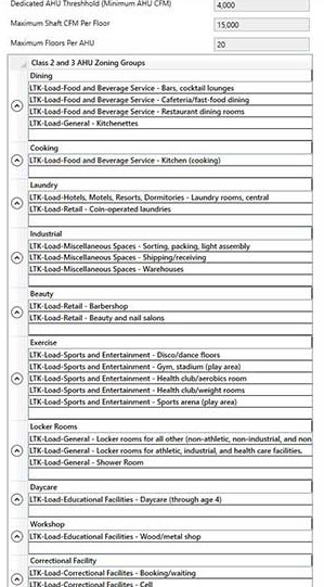
ASHRAE 62.1 allows Class 2 air to be recirculated to other Class 2 or 3 spaces that involve the same space pollutant sources. Therefore, if our aerobics room had an adjacent weight room, those two spaces could be put on the same AHU, and air could be returned and distributed between the two rooms. To accelerate the zoning process, firms should assemble a default list of ASHRAE 62.1 space types that can be assumed to have similar pollutant types. See Figure 1 for an example.
ASHRAE 62.1 5.13.2.3 allows the redesignation of Class 1 spaces to Class 2 spaces if the Class 1 spaces are ancillary to the class 2 spaces. For example, a gym coach’s office connected to the weight room could be reclassified as a Class 2 space, even though offices are typically Class 1. Therefore, air from both spaces could be returned and redistributed from a common air-handling unit.
The question then becomes, at what point should a dedicated AHU be provided to groups of Class 2 and 3 spaces instead of exhausting them? Depending on the operating hours, climate, and local utility rates, outdoor air costs roughly $2 - $10 / cfm / year. Smaller AHUs cost $10/cfm. Installing a 4,000-cfm unit instead of exhausting (and making up) 4,000 cfm would net a five year simple payback. ($10/cfm * 4,000 cfm) / ($2/cfm/year * 4,000 CFM) = five years. Therefore, if adjacent Class 2/3 spaces in similar pollutant groups (figure 1) require more than approximately 4,000 cfm of air conditioning, putting them on a dedicated AHU is probably a good idea.
Geometry
As discussed in the building economics discussion, HVAC systems affect building geometry in two ways: the duct geometry takes up plenum space, and mechanical rooms take up floor space. Both should be minimized for the most cost-effective building.
Duct geometry can drive zoning decisions because it can drive plenum height requirements. Taller plenums require taller buildings, which increases the project cost. HVAC systems typically have rectangular ducts with large width-to-height aspect ratios to minimize the plenum space required for MEP elements.
There are also equipment limitations to the plenum height. It is pointless to drive your duct size down to 10-inches-by-100 when, at some point, a 16-inch tall VAV must fit plenum space. For this reason, a good duct height target is 18 inches tall. An 18-inch tall duct will allow a 1-inch flange on the top and bottom of the duct with a 16-inch tap takeoff, allowing easy connections to 16-inch VAVs.
As the aspect ratio of the duct gets larger (more rectangular, less square), ducts are less efficient at carrying air, so engineers must balance duct cost-effectiveness with reasonable plenum space demands. At a 4-to-1 duct aspect ratio, many assumptions about air pressure loss calculations begin to break down, and the K-factors of duct fittings start to increase exponentially. Therefore, a 4-to-1 duct aspect ratio is a reasonable maximum.
Given an 18-inch target duct height and a 4-to-1 maximum duct aspect ratio yields an 18-inch-by-72-inch maximum duct size target to distribute in a plenum space. An 18-inch-by-72-inch duct can carry about 15,000 cfm at 0.1 in. W.C./100’. So, if each floor is grouped into approximately 15,000 cfm groups and provided with a shaft, the plenum space required on each floor can be minimized.
Once you’ve determined the maximum cfm/shaft/floor, typically approximately 15,000 cfm/shaft/floor, you can pair that with your building geometry.
Shafts allow the large AHUs to be shifted to less desirable areas of the building that can’t be used anyway, such as rooftops, basements, or interstitial floors that correspond with structural requirements. However, as more floors are added to the shaft, the vertical portion of the shaft gets larger and larger to accommodate the increased airflow. When a shaft serves more than 20 floors, the shaft area required gets larger than a mechanical room that could house an AHU to serve that floor7. Therefore, buildings should be divided into a maximum of 20-floor increments and served by multiple AHU mechanical rooms distributed vertically throughout the building. For example, a 30-floor building could be served with AHUs on the 15th floor serving floors 1-15 and AHUs on the rooftop serving floors 16-30. This method typically works well with high-rise structural systems, which require belt walls that make the floor unusable to tenants.
All things being equal, err with zoning AHU zones on an east-west axis so that the morning peak loads on the east side of the building do not coincide with the peak loads on the west side of the building, which occur in the afternoon. This will maximize your equipment diversity. As the energy code drives exterior loads down, this is becoming less important but is still good practice.
VAV Zoning Example
Consider zoning a three-story building with 45,000 cfm per floor. The building could be zoned for one AHU in a mechanical room on each floor. However, this leads to two problems. First, the mechanical room takes up valuable usable space on the floor, and second, when the duct exits that mechanical room, it would require a 28-inch-by-112-inch duct size at 0.1 in. W.C./100 feet and a plenum to accommodate. If, on the other hand, you put three AHUs on the roof (hopefully in a penthouse) that each served a shaft which served all three floors, the air could be distributed air with the same amount of AHUs, but limit the maximum duct size in each plenum to 15,000 cfm. This arrangement would maximize usable floor space while limiting the required plenum height.
While the AHU drives the ventilation zoning of the building, the terminal unit drives the thermal zoning of the building.
VAV zoning has two major considerations that must be balanced: cost and comfort. If cost is not an issue, every space should be assigned a dedicated VAV and thermostat. That space will be controlled to the space temperature set point, creating the optimal comfort for the occupant.
In most situations, when the cost is a consideration, similar spaces can share a VAV.
Ideally, every space that shares a VAV will have an identical load profile. If the spaces do not share an identical load profile, the space without the thermostat will “drift” away from the set point and become uncomfortable.
For example, consider two offices on a single VAV. Ideally, they both have the same exterior exposures, and the occupants arrive and leave at the same time every day, use the same plug load, and never take a day off. In practice, this never happens. The office with the thermostat will sometimes be unoccupied when the other office is occupied. The occupied office will have a drastically different load profile and will be well off the temperature set point.
Because it is unrealistic to match load profiles exactly, the next best approximation is to match loads as closely as possible. For example, this will force corner offices with two exterior exposures, to not be zoned with adjacent single-wall exposure offices.
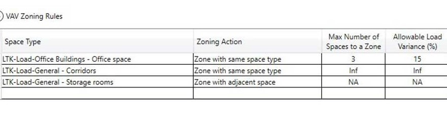
Some spaces, such as unoccupied storage rooms, need to be “lightly” conditioned to prevent freezing and spare the temporary occupants from getting a blast of heat when entering. These spaces can be zoned with any adjacent space, even when the load profiles drastically differ. The intent here is not to maintain human comfort but to temper the space. Similarly, transient spaces, such as corridors, are less about human comfort and more about tempering the space. Again, these can be zoned together but with a larger allowable peak load difference.
These space types and corresponding rules can be compiled in a figure similar to Figure 2.
The author has often seen HVAC designs attempting to break a single, continuous, open area into two different zones — one covering the exterior and one covering the interior. In every instance, the author has seen this in practice, he has observed one VAV in full cooling, attempting to maintain its thermostat setting, and the other VAV in full heating, attempting to maintain its thermostat setting. The VAVs are essentially introducing false load to the other VAV and providing a direct transfer of energy from the boiler to the chiller.
In the author’s experience, you can’t maintain two different temperatures in one continuous space.
If multiple VAVs are to be used in an open area, they should operate with the same control signal, even if that control signal comes from multiple thermostats and the control signal is calculated based on an average or a worst-case scenario.
Bringing It All Together
Zone AHUs:
- Determine which adjacent ASHRAE 62.1 Class 2 & 3 spaces have similar pollutant groups (see Figure 1 for an example), if they are above the Dedicated AHU Threshold size, assign those spaces to a dedicated AHU.
- Decide the maximum shaft cfm per floor. This will typically be around 15,000 cfm.
- Decide the maximum number of floors per AHU; in low-rise buildings, this will typically be all of them; in high-rise buildings, this will typically be the number of floors separated by the structural belt system, or a maximum of 20.
- For each floor on the AHU, determine how many shafts are required. Shafts required = floor cfm / max cfm/shaft.
- Divide each floor into as adjacent and as equal-sized groups as possible with a target cfm = floor cfm / shaft cfm. All things being equal, err with zoning AHU zones on an east-west axis.
- Combine floor groups vertically into stacks and assign each stack to an AHU.
Zone VAVs:
- Determine a list of VAV zoning rules for each space type that can reasonably be zoned together, the rules should include what types of spaces they can be zoned with, the maximum number of spaces to zone together, and the allowable load variance. These rules will be highly dependent on how the building owner prefers upfront cost vs. ongoing comfort. An example is shown as figure 2.
- For each floor served by each AHU, group the space types that can be zoned together, and compare the peak heating and cooling loads and adjacencies. If they can be zoned together, assign them to a single VAV Zone.
As described in this paper, HVAC zoning is a complicated and time-consuming process. Thankfully, this process has been automated for BIM projects.
References:
- Rock, Brian A, PH.D, PE. Art or Science? Thermal Zoning For HVAC Design. ASHRAE Journal, December 2018.
- ASHRAE. 2021. “Fundamentals Handbook”. Ch 19.15.
- Ripple HVAC Toolkit. Ripple HVAC Toolkit | Revit | Autodesk App Store.
- Stein, Jeff, PE. Taylor, Steven, PE. VAV Reheat Versus Active Chilled Beams & DOAS. ASHRAE Journal, May 2013.
- ASHRAE. 2022. “ASHRAE Standard 62.1 Ventilation for Acceptable Indoor Air Quality”.
- Taylor, Steven T. PE, “Designing Mega-AHUs”. ASHRAE Journal, April 2018.


