
Buildings require various levels of temperature and humidity controls, but when it comes to preserving historical artifacts or performing an operation, the temperature and humidity levels in a space become crucial to keep a building operational. For instance, a typical office building will require a space temperature of 75°F ± 2°F and a humidity level of 50% ± 5%; however, a typical museum gallery may require a space temperature of 70°F ± 2° and a relative humidity (RH) of 45% ± 5%. Museums, hospitals, and lab buildings all generally need stricter temperature and humidity set points, making psychrometric analysis an important step in the design of the HVAC systems that serve these types of buildings. A psychrometric analysis involves using a psychrometric chart, as seen in Figure 1, to determine the dry bulb (°F), wet bulb (°F), dew point (°F), RH (%), humidity ratio (gr/lb), and enthalpy (btu/lb) of air at a given condition. Moving the plotted point in different directions on the chart represents various ways of conditioning the air, as seen in Figure 2. With strict operating conditions, humidifying and dehumidifying strategies will need to be set in place in order to condition the air to a precise location on the psychrometric chart.
For example, take an interior 10,000-square-foot interactive museum gallery located in Washington, D.C., that has 20% outside air, a lighting power density of 1 W/ft2, a plug load of 5 W/ft2, and an occupancy of 400 people. From this, the sensible heat ratio, which is the sensible heat load divided by the total heat load, can be determined to be 0.79. The sensible heat ratio is used in tandem with the psychrometric chart by plotting the ratio, or slope, on the chart running through the space temperature and RH set points. Supply air must fall on this line in order to properly condition the space due to the specific sensible and latent load present.
As seen in Figure 2, the museum gallery is required to operate at 70° dry bulb and 45% RH. The outside air condition can be taken from ASHRAE climatic data, which, in this summer for Washington, D.C., is 92° DB and 74.7° WB. The mixed air condition can be determined by drawing a line between the return and outside air points, with the mixed air condition being based off the proportion of return air versus outside air. During summer, the mixed air is sent through a cooling coil to dehumidify and cool the air as seen in Figure 2. Typical cooling coils cool air down to 50°-52°; however, the room condition of 70° DB and 45% RH has a dew point of 47.7°. Exhibit spaces, in particular the immersive type, tend to experience high occupancy rates almost instantaneously and for periods of 30 minutes to two hours. This means that sizing a cooling coil to cool air below 47.7° to avoid condensation in the space may not suffice; the cooling coil will need to have enough additional capacity to address these high ‘instantaneous’ space sensible and latent loads. These authors recommend using no more than 3° chilled water approach with 40° chilled water entering temperature into the cooling coil in order to achieve a cooling coil leaving air temperature of 43°. Once the air is cooled to 43°, the air is require to be reheated to be on the sensible heat ratio line. The reheat can be done indirectly by having the chilled water coil upstream of the supply fans and by using the reheat coils at the terminal units.
The resulting supply air condition is 57.7° DB and 50.7° WB, which will provide proper sensible and latent cooling the museum gallery requires.
 FIGURE 1: A psychrometric analysis involves using a psychrometric chart to determine the dry bulb (°F), wet bulb (°F), dew point (°F), relative humidity (%), humidity ratio (gr/lb.), and enthalpy (Btu/lb) of air at a given condition. Images courtesy of SmithGroup
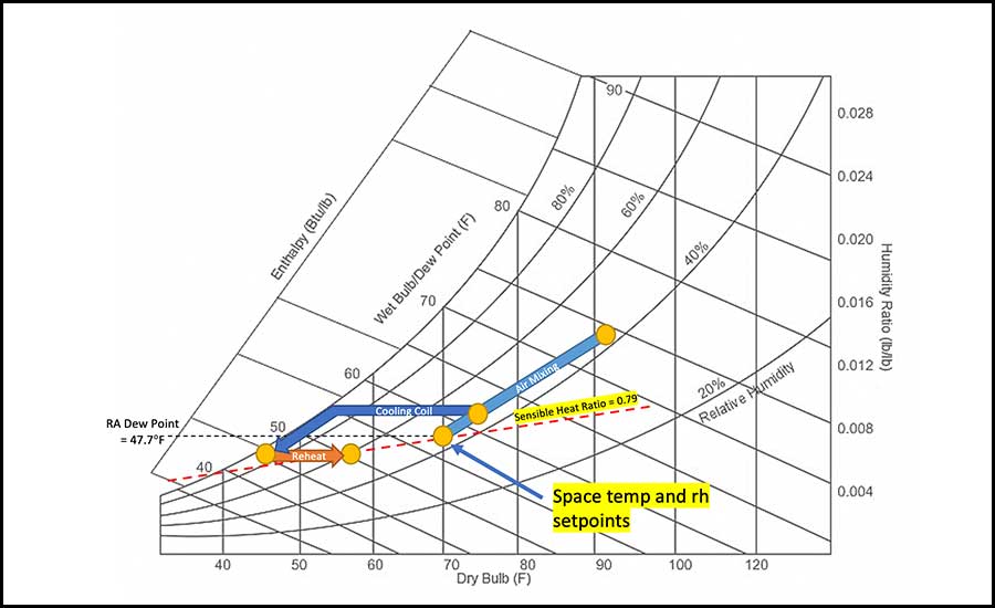 FIGURE 2: Moving the plotted point in different directions on a psychrometric chart represents various ways to condition indoor air.
An example of sequence of operations to control dehumidification in an air-handling unit could be as follows:
- Any of the space RH sensors shall override the cooling sequence to maintain a maximum of 45% RH (adj.) for the area served by the air-handling units;
- If space RH is greater than maximum set point and current reset discharge air temperature set point (DATSPT) is above initial, then reset to the initial DATSPT;
- If after 15 minutes (adj.) the space RH is still greater than maximum the set point with initial DATSPT, then continue to incrementally reset down DATSPT to 43°; and
- If all the space RH sensors and unit return RH sensor read 44% RH or below, then the building management system (BMS) shall exit dehumidification mode.
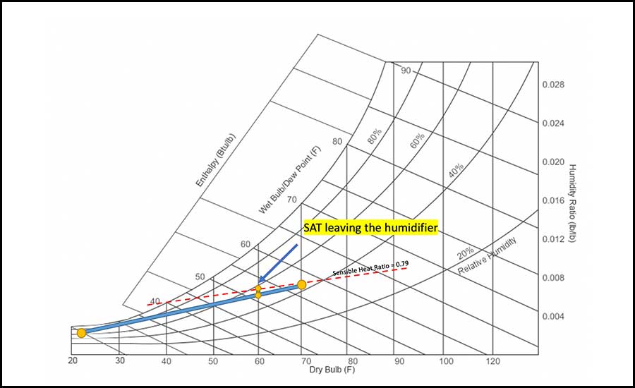 FIGURE 3: In the winter, typically, humidification becomes a necessity as outside air becomes dryer and colder. In the Washington, D.C., example, since the internal loads have remained the same, the sensible heat ratio is maintained at 0.79. Plotting this slope on the chart, the mixed air condition falls below the line, indicating that air provided at this condition will end up dehumidifying the space below the strict room set point.
In the winter, typically, humidification becomes a necessity as outside air becomes dryer and colder. For Washington, D.C., the ASHRAE climatic design conditions are 21.6° DB and 20.8° WB. Maintaining the same internal load conditions as in the summer dehumidification mode, the mixed air temperature is determined to be 60.3° DB and 51.4° WB as seen on the psychrometric chart on Figure 3. Since the internal loads have remained the same, the sensible heat ratio is maintained at 0.79. Plotting this slope on the chart, the mixed air condition falls below the line, indicating that air provided at this condition will end up dehumidifying the space below the strict room set point. To increase the moisture content of the air to move the psychrometric point up to the sensible heat ratio line, a humidifier in the air-handling unit (AHU) would be initiated to inject steam into the airstream. After humidification, the supply air temperature to the space becomes 60.4° DB and 52.2° WB.
An example of sequence of operations to control air humidification in an AHU would be as follows:
- The controller shall monitor the corresponding space RH sensors and use as required for humidification control;
- The space RH set point shall be 45% (adj.);
- The steam control valve shall modulate to maintain the space RH. The humidification control shall be enabled whenever: A) Any of the space RH sensors read values at or below 43% (adj.) and B) the supply fan status is on; and
- The humidifier shall be disabled whenever supply air humidity rises above safety high-limit cutout of 95% (adj.).
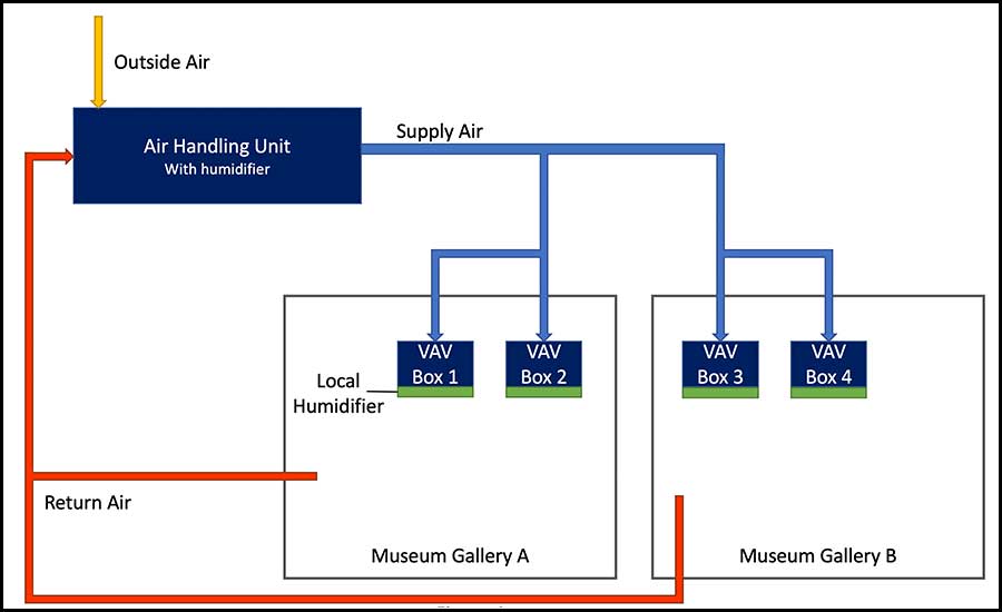 FIGURE 4: As shown here, Museum Gallery A may have a drop in relative humdity while Mueseum Gallery B remains within the desired set point.
An alternative method for winter humidification in spaces with strict humidity requirements is to use trim humidification. This strategy is typically implemented by having a humidifier at the AHU and used to humidify the supply air up to the equivalent of 35% space RH and then relies on local/trim humidifiers at VAV boxes to supply the zones with additional humidification as required. As seen in Figure 4, Museum Gallery A may have a drop in RH while Museum Gallery B remains within the desired set point. The controllers for VAV boxes 1 and 2 will initiate their own humidification sequence initiate, allowing the RH set point in Gallery A to be met while Gallery B remains unchanged.
Another aspect to controllability of space set points is the sensor repeatability of the physical thermostats and humidistats in the spaces. A typical industry standard thermostat/humidistat has the ability to accurately read the temperature of a room within ±0.9°F and RH within ±5%. For spaces that require tight temperature and humidity control, the standard accuracy readings may not be reliable enough to properly operate the space. For instance, the RH set point for a room may be 35% ± 2%. The range of ± 5% accuracy in the standard humidistat will not be sufficient to properly determine if the space is operating its specific range, as more accurate temperature and RH sensors may be required. Similarly, the repeatability of each sensor is very important. The higher the repeatability range, the higher the risk of having the space temperature and RH go outside of the desired range of operation.
Dehumidification may also be necessary in the winter if a humidifier valve fails at the exhibit level, causing the RH to increase beyond the set point. Due to the already cold and dry outside air available in the winter, the AHU would modulate the outside air damper to increase the intake of dry outdoor air. By providing an increased percentage of outdoor air, the mixed air may need to be reheated to avoid subcooling of the zones, allowing neutral dry air to be supplied into the exhibits.
Good and valid dehumidification and humidification analyses cannot be done without having a strong understanding of the ‘famous’ psychrometric chart.


