


Editor’s Note: Part 1 of this two-part series was published in the June 2020 issue of Engineered Systems. See Part 1 at https://bit.ly/ESMOTORS.
A variable-speed drive (VSD) may be provided with a bypass to allow a motor to continue receiving power in the event of VSD failure. This is accomplished by specifying the VSD to be provided with a switching mechanism that disconnects the motor power supply from the VSD output and reconnects to the output terminals of the bypass mechanism, thus circumventing the failed VSD module.
The motor (fan or pump) served by the VSD may not be allowed to tolerate a long interruption of power. This may be an owner request, a mechanical design requirement, or a National Electrical Code (NEC) requirement as in the case of an air handler serving an operating room. To ensure continued operation of a critical HVAC load, a VSD can be specified with a bypass mechanism that is automatic, manual, or field-selectable automatic/manual. The control function of the bypass must also be specified. The control function can be (in increasing order of cost and complexity) an across-the-line starter, a reduced-voltage magnetic starter, an electronic (soft) starter, or a redundant VSD. If automatic mode is desired or necessary to minimize power supply interruption to critical HVAC equipment, the control function of the bypass should be closely coordinated with the mechanical designer. If, for instance, a VSD serving a fan goes into automatic bypass mode and the bypass control type is across-the-line, the fan will go to 100% operation, which could be problematic if downstream duct louvers/dampers are not first adjusted for 100% fan operation.
VSD and Motor Disconnect Means
NEC (2020), Articles 430.102(A), and 430.102(B), require a disconnecting means for the VSD and for the motor. The NEC (2020), 430.102(B), allows one disconnecting means to fulfill both requirements. Typically, a VSD can be specified with an integral input disconnecting means that fulfills the requirements of the aforementioned NEC articles. Although not always mandated by the NEC, some designers provide a disconnecting means at the motor as a good design practice to ensure power does not reach the motor during maintenance and other nonoperating times. In some cases, the motor may be mounted on the roof or in an area where it is not desirable to locate a VSD, or the VSD cannot otherwise be located within sight of the motor. When a local disconnect is provided at the motor (i.e., between the VSD output terminals and the motor), it is recommended to provide the disconnect with a fast-acting auxiliary contact that will trigger a freewheel stop[6] on the drive before the main 3-phase contacts open. A motor local disconnect should not be opened or closed while the VSD is running as this can damage the output IGBT7 components of the drive. Consult with the VSD manufacturer for proper protection.
When a local disconnect is provided at the motor (i.e., between the VSD output terminals and the motor), some FSD manufacturers recommend the motor local disconnect be provided with a set of fast-acting auxiliary contacts that will signal the VSD to disengage the motor just prior to the opening of the disconnect line power contacts to avoid possible damage to the drives output IGBT6 module. Consult with the VSD manufacturer for proper protection.
VSD to Motor Distance
The use of IGBT technology and pulse width modulation (PWM) for shaping and controlling the output waveform received at the motor has greatly improved motor control. On the downside, this technology has introduced the problem of reflected waves. A discussion of reflected waves is beyond the scope of this article, but it can be noted that reflected waves cause voltage spikes that can damage the motor and the conductors serving the motor. Overvoltage and its damaging effects can be prevented, or significantly reduced, by keeping the length of the conductor from VSD to motor as short as possible and less than the VSD manufacturer’s maximum length limit. Where design conditions require a length exceeding the manufacturer limit, other methods, such as the addition of a reactor, filter, or other type of terminating device, can be considered. Consult the VSD manufacturer for the recommended optimum solution.
Electronically Commutated Motors (ECMs)
Direct current motors are not typical for the majority of HVAC applications. DC motors are, however, discussed in this article, since a specific type of DC motor known as an ECM is finding its way into HVAC applications.
Two types of DC motors are discussed:
DC brushed and DC brushless (also known as ECM). DC motors are similar to AC motors in that they both have a stationary component (stator) and a moving component (rotor). Unlike AC motors, DC motors are powered by direct current. Direct current does not have an alternating polarity as is necessary in an AC motor to establish a stator rotating magnetic field.
AC and DC motors rely on the interaction of magnetic fields set up by electromagnets. While an AC motor uses electromagnets in both the stator and the rotor, the DC motor uses electromagnets in its rotor only and uses permanent magnets in its stator.
Brushed DC Motor
A brushed DC motor employs metal contacts, or “brushes,” and a rotating ring that is split into two equal halves with no electrical conductivity between them. This split-ring is known as a “commutator.” One half of the commutator is connected to the end of the rotor winding, and the wire at the end of the winding loops back to connect to the other half of the commutator. Each half of the commutator is in contact with a fixed contact known as a brush. The brush provides electrical connection between the moveable commutator and the positive and negative terminals of a DC power supply. Current flowing from the DC power supply through the rotor windings creates a magnetic field that interacts with the stator field and rotation begins. At every 180 degrees of rotation, the position of the north and south poles of the rotor reverse polarity. To maintain torque in a constant direction, the current flowing through the rotor windings must also reverse polarity. As the commutator is connected directly to the rotor, it also rotates with each half of the commutator, alternating between connection to the positively connected and connected brushes, thus simulating an alternating current in the rotor.
DC motors, compared to typical drive-controlled AC motors, have greater controllability, such as high-precision, quick-response-time speed control, and the ability to maintain maximum torque across almost the entire speed range. AC motors using VSDs and employing vector-control algorithms can provide performance comparable to DC motors. In recent years, a new type of DC motor, an ECM, is finding its way into HVAC applications with ratings up to 20 hp. An ECM is a DC motor powered from an AC source and is provided with an onboard controller that provides many of the functions of a VSD but in a smaller package.
ECM, Brushless Motors
An electronically commutated motor is a DC motor design that replaces the commutator and brushes with a solid-state electronic controller. The electronic controller monitors the angular position of the rotor and provides the optimum value of voltage necessary to achieve the rotor speed required for the load. An ECM is typically provided with an onboard controller specifically matched to the motor it operates. The onboard controller design results in a smaller footprint than is required for a traditional-type motor and controller installation.
Motor Design Considerations
Utility power is delivered to a building or installation in the form of a sine wave. Building loads that are linear (or passive) draw this power in the same manner as it is delivered. In other words, linear devices do not act upon the power signal, resulting in a distortion of its sine wave shape. Nonlinear (or active) loads on the other hand will affect the shape of the incoming power signal, altering its shape from a sine wave. Most commonly, the fundamental difference between a linear and nonlinear load is a nonlinear load frequently employs a switched-mode power supply in the case of office equipment, computers, etc., or uses where inverter technology is found in uninterruptible power supplies and VFDs, where the incoming AC signal is rectified in to a DC signal, and the DC signal is inverted back to an AC signal. When a switched-mode power supply or inverter draws power, it does so in intermittent time increments (or pulses) rather than a continuous draw as is the case with linear loads. The result is a signal that is alternating but no longer has a sine shape. The original sine wave (60 Hz) is still present in the way in which nonlinear loads functions’ have added additional sine waves at integer multiples of the fundamental frequency (i.e., 60 Hz). The vector addition of the original sine wave (fundamental) and the sine waves occurring at multiples of the fundamental frequency results in a distorted wave form that can have a negative effect on other equipment, including increased heating in conductors.
As the use of switch-mode power supplies and inverters have increased so too has harmonic content in power distribution systems. To address the issues and concerns associated with harmonic content and its effects on electrical distribution system power quality, the Institute of Electrical and Electronics (IEEE) maintains Standard 519, “Recommended Practice and Requirements for Harmonic Control in Electric Power Systems” first published in 1981.
IEEE describes procedures for calculating harmonic content and gives recommendations on harmonic content’s maximum acceptable levels.
Harmonic Content Mitigation Methods
The following are some methods of reducing harmonic content within a facility.
Passive harmonic filters (PHF) are based on a network of passive electrical components and may be constructed of resistors (R), inductors (L), and capacitors (C), such as an LR filter or an RLC filter. A filter is tuned to a specific harmonic frequency in order to eliminate or attenuate the signal at that frequency before it reaches equipment. Passive filters are usually best suited for individual motor applications. A passive filter behaves in a way similar to a notch filter that is used in audio electronics.
Multiple VSD Applications
Active harmonic filters (AHF) use solid-state technology to detect and cancel or attenuate harmonics. Unlike passive filters, active harmonic filters can be applied to several motors. AHFs can also be applied to multiple harmonic frequencies. One method using AHFs to eliminate a harmonic. Once detected, the AHF injects a current of the same frequency but shifted 180 degrees so as to cancel the harmonic.
VSD Pulse Quantity
Harmonic content associated with a VSD is inversely proportional to the number of pulses used in the VSD design. Harmonic content is reduced when moving from a 6-pulse unit to a 12-pulse unit and is reduced further when using an 18-pulse unit. Refer to NEC Article 430.6(C) for sizing of overcurrent protective devices and conductors.
Case Study — AHU Fans
A common occurrence in which engineers must choose between the motor control technologies is in the design of air-handling unit (AHU) fan systems. Modern AHU designs typically feature multiple fans and variable-speed controls to reduce an AHU’s footprint and energy consumption and to provide redundancy. With the recent increase in available ECM sizes, engineers can now choose between AC induction motors with VSDs and ECMs for applications in which the total static pressure requirement is at or below approximately 6 inches water gauge.
A comparison of ECM- and VSD-based fan arrays is provided in Figure 3. Designing a fan array using ECM fans is a straightforward process. The quantity of motors/fans is generally proportional to airflow due to the motor size limitations. When using VSDs, numerous options exist since the fan size, fan quantity, and fan-to-VSD ratio are all highly adjustable. For the purpose of this comparison, two fans were used for the VSD option for the 10,000-cfm AHU, and four fans were used for the larger AHUs while their size was adjusted to provide the design airflow. All VSD cases were completed based on one VSD per fan. The cost data is based on a popular fan and drive manufacturers and represents unit cost as opposed to installed cost. The cost is inclusive of the fan, motor, and drive.
The results of the comparison show that the ECM fan arrays result in slightly lower first cost than the VSD fan array; however, the following considerations should be taken into account:
- ECMs create more harmonic distortion than standard VSDs. The use of ECMs may require the facility to add harmonic filtration or make use of specialized low harmonic VSDs for pumps or other large loads in the facility in order to comply with IEEE 519. The cost to transition from a standard VSD to a low-harmonic VSD for a single 40-60 HP pump can erase the cost savings of the ECM fan arrays shown below.
- The ECM cost does not include a local display. If a local display is desired, the ECM cost will increase.
- The cost data is based on the use of removable plates to isolate fans that have failed as opposed to backdraft dampers.
- The data does not include the cost of fan inlet-mounted airflow measuring stations.
- The data does not include the cost of a motor replacement rail.
Footnotes
(1) Equivalence of force equations for a gravitational field and an electric field:
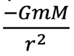
Gravitational field:
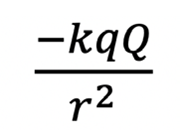
Electric field:
(2) A magnetic pole cannot exist independently and must always be paired with another magnetic pole of opposite polarity. [Gauss’ Law for Magnetism]. A magnetic field always flows from the ‘north’ pole to the complimentary ‘south’ pole. The number of poles is always a multiple of 2.
(3) Clarke Transform - converts the time domain components of a three-phase system (in abc frame) to two components in an orthogonal stationary frame
(4) Park Transform - converts the two components in the  frame to an orthogonal rotating reference frame (dq0)
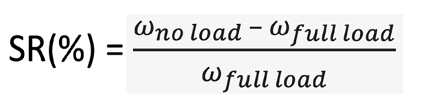
(5) Speed regulation:
(6) IGBT. Insulated Gate Bipolar Transistor. A solid-state switch combing the high-speed switching ability of Field-effect transistor and the high-power rating of a bipolar transistor.


