
Properly caring for a boiler pressure vessel and its associated refractories is important to ensure the longevity and reliability of the system. In addition to routine maintenance, it is critical to understand the warning signs of a boiler system failure and how to remedy the situation.
First, one must understand that the pressure vessel is a heat exchanger that absorbs heat from the burner and converts it to either steam or hot water. Very sophisticated engineering goes into its design, including calculations for varying temperatures, mass flow, velocities, heat fluxes, and efficiency, as well as various calculations for determining metal deformation limitations and tensile strengths.
PRESSURE VESSEL COMPONENTS
The pressure vessel in a firetube boiler consists of four distinct elements: a shell, furnace, tube sheets, and tubes. The number of tube sheets differs based on whether it is a wetback or dryback design. A wetback design includes three tube sheets, and dryback design includes two (Figures 1 and 2).
The shell is the vessel that contains the water surrounding the furnace and tubes along with various tappings accommodating the steam or hot water outlet to the system, connections for level controls, pressure/temperature sensors, water and chemical feed, blow down, etc.
A boiler’s furnace can be either corrugated or plain and is chosen based on cost and pressure considerations with one design having no distinct advantage over the other.
The tube sheets are welded within the shell and anchor the furnace and tubes.
 FIGURE 1. Wetback boiler.
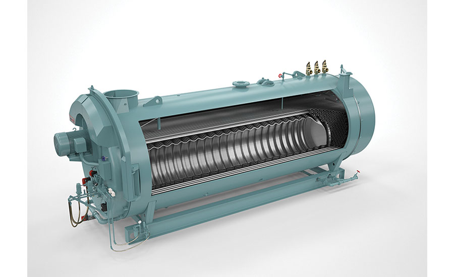 FIGURE 2. Wetback boiler.
The tubes, which are rolled, beaded, welded or flared into the tube sheet, are typically plain, but in certain designs they may include extended surfaces, especially in the second (hot) pass of a multiple pass boiler.
The thickness of steel used to withstand the pressure and welding requirements will vary by code. Low-pressure steam (15 psi) and hot water boilers (less than 250ºF and 160 psi) are constructed per ASME Code Section IV, while high-pressure boilers operating at more than 250ºF saturated need to be constructed per ASME Section I, which includes full-penetration welding, heat treating in some instances, and X-raying.
INSULATING REFRACTORIES
The refractories in a firetube boiler exist for two reasons: to provide protection for metal overheating and, in the case of the burner throat tile, to also assist in the combustion process.
In the furnace is the burner throat tile and the furnace liner (Figure 3). As noted, the throat tile insulates and seals the very-high-temperature products of combustion from damaging the surrounding steel-burner housing, and it also assists in combustion by concentrating the combustion mix and heat while shaping it into the furnace. The liner is there to insulate the furnace from the extreme radiant heat at the very front of the chamber.
The other insulating refractories are found in the access doors of the firetube boiler, both front and rear.
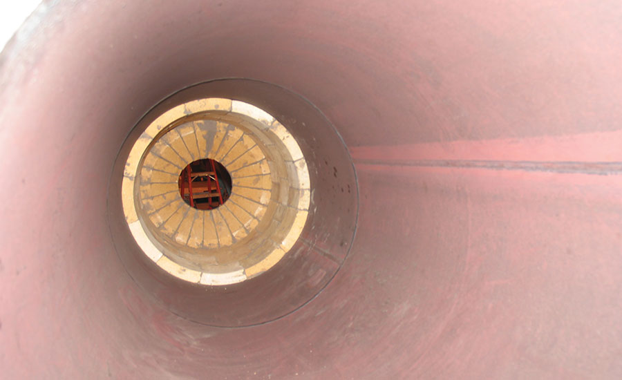 FIGURE 3. Furnace liner and throat tile.
In the case of an older dryback boiler, the rear door is filled with refractory, both high temperature on the bottom of the door and a lower temperature material on top. It may also include a directional baffle made of mortar and brick, or it may be of monolithic construction with mortar. Today’s dryback boilers are built with poured refractory in the lower section and blanket insulation with a wire screen in the upper section.
In a wetback boiler, the rear access is a plug containing high-temperature refractory. A majority of wetback boilers use blanket insulation and screening in the front and rear doors. The dryback will also have this material in its front door.
SIGNS OF PRESSURE VESSEL PROBLEMS AND POSSIBLE SOLUTIONS
The primary causes of pressure vessel failures are sooting/scaling, corrosion, and thermal shocking of the vessel.
When the boiler has produced heavy soot on the fireside surface, it insulates and reduces heat transfer significantly, and leads to a loss of efficiency. The same is true of the waterside surfaces if they accumulate heavy scale. As little as 1/8-in of scale or soot can drive fuel costs as much as 25% higher while also dramatically contributing to pressure vessel failure of the tube sheets, furnace, and tubes.
When this occurs, the first sign is a fairly dramatic rise in stack temperature above normal, due to the lack of heat transferring to the water-backed surfaces of the vessel. Or, when the boiler is down for any length of time, there may be evidence of water leaking in the front or back of the unit. Also, there is the possibility of oxygen pitting (corrosion) from the waterside of the tubes, allowing water to enter the tube’s inner fireside and leak to the floor.
Thermal shock damage is due to a radical difference in the feedwater temperature entering the boiler and will most likely be found with evidence of tube and tube sheet leaking, along with possible cracking of the feedwater connection into the boiler.
To solve the scaling and corrosion problems in the boiler, first ensure that a proper and regular blowdown procedure, both surface and bottom, is enforced and engage a qualified water treatment expert to recommend proper chemicals and dosing to eliminate the corrosion and scaling. Also consider a deaerator for greatly mitigating the free oxygen in the feedwater, reducing the need for chemicals and excessively frequent surface blowdown, saving energy dollars.
The sooting problem is a combustion issue that requires the skills of a qualified technician who will take readings and adjust the fuel/air ratio throughout the burner’s turndown range. The key is to allow enough excess air to prevent a rich (sooting) mix, while keeping the excess air at a safe yet acceptably efficient point while modulating from low to high fire.
The thermal shock problem is quite common and can be either cold or hot shock. Typically, it is cold shock that causes the pressure vessel to quickly contract, putting inordinate strain on the welds and tube sheet ligaments.
The solution is to make sure the feedwater entering the boiler is as close to its saturation temperature as practically possible. This is yet another reason to consider feeding the boiler with a deaerator, a pressurized vessel using the boiler’s steam to elevate the feedwater temperature to drive off the corrosive gasses (oxygen and carbon dioxide).
Normally, the deaerator operates at about 5 psig (227ºF); however, it can operate at higher pressures/temperatures if the boiler is operating in the higher ranges above 100 psig (338ºF). The key is to reduce the difference between the feedwater temperature and the boiler’s operating temperature as much as practically possible.
SIGNS OF REFRACTORY PROBLEMS & POSSIBLE SOLUTIONS
As noted earlier, the refractory in firetube boilers is found in the burner and furnace areas and the access doors.
The first sign of failure with access doors may again be a rise in stack temperature above normal because of a directional baffle or seal failure allowing hot gas to bypass some passes through the boiler. Or, there may be visual signs with outer painted surfaces turning white or losing paint entirely. Normally the causes for this type of failure are a damaged internal directional baffle, and/or a damaged gasket or poor sealing due to improper tightening of the door after closing. Another cause of overheating and door failure can be combustion vibration (rumbling), causing the refractory to crack and break out.
The solution in these cases is to repair the problem immediately, which will prevent extensive damage to the door that will require a complete replacement. The repair often can be made on site using manufacturer-approved materials normally consisting of high-temperature bonding mortar or a plastic-like filler used to fill in the large cracks and void areas. The baffle can most likely be repaired with a combination of high-temperature brick and bonding mortar. A monolithic door /baffle combination can also be poured in the field, using a properly sized form after the old refractory has been removed.
Following the repair, a light wash coat using a diluted high-temperature bonding mortar is recommended. It should also be noted that cracks in the door(s) that are 1/8-in wide or less are expansion cracks that will reseal themselves when the boiler is firing.
Diagnosing failures with the burner throat and furnace liner are primarily visual, detected either by seeing compromises, such as extensive cracking, or missing chunks through the rear sight port at the back of the boiler or during the time the boiler is down for inspection.
Another possibility is a combustion problem caused by a failure of the burner throat seal to the burner housing (Figure 4). This does not only cause combustion problems with excessively high or low excess air in the combustion mix, but it also can cause overheating of the steel burner housing, leading to cracking of the steel that requires an immediate welding repair or replacement.
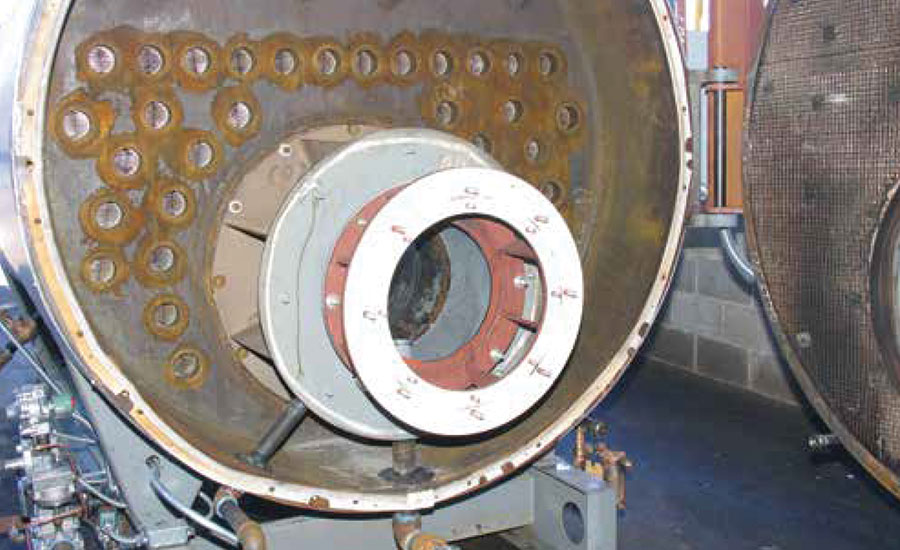 FIGURE 3. Burner housing before throat installed.
If the burner throat tile piece(s) is cracked or broken, it needs to be replaced as soon as possible with an equivalent product per the manufacturer’s instructions. The same is true for the furnace liner. In this case, if a piece is replaced, the old mortar sealing the tile to the furnace needs to be scraped away and new mortar applied, including sealing the joints with a high-temperature bonding mortar.
In the final analysis, all the components in a boiler are important and contribute to its efficiency, reliability, and safety. That is why it is critical to maintain an accurate Boiler Room Log, documenting all the operating essentials on a routine basis — daily, weekly, monthly, semi-annually, and annually. It is this discipline, along with ongoing training of operating personnel, that not only saves countless energy and operational dollars but also preserves the safety and wellbeing of everyone in the building.


