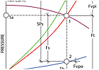
FIGURE 1. Basic graphical expression for total, static, and velocity pressure in a working vent system.
The selection of a proper fan for a vent system must pursue the proper basis. This is an essential element in the engineering design phase of a vent system.
However, many controversial articles in engineering journals and other literature consider contradictive bases for selection1 through 6. Those articles notwithstanding, the natural laws of aerodynamics have strict requirements that do not allow contradictions.
This article presents graphical illustrations as the clearest demonstration of the fan selection procedure, with trade-offs between system and fan curves, air capacity and pressure, and energy consumption.

FIGURE 1A. Illustration of pressure values in the working vent system.
GRAPHICAL ILLUSTRATIONS OF AERODYNAMIC COMPONENTS IN A VENT SYSTEM
Fan and air ducts together with their associated parts comprise a vent system. Figures 1 and 1a illustrate the relationship of all existing pressures in the working system, where:Ft - fan total pressure - system total resistance
Fvpo - fan outlet velocity pressure
Fvpi - fan inlet velocity pressure
Fs - fan static pressure
SPs - system total static pressure TPi and TPo - inlet and outlet system total pressure at a point SPi and SPo - inlet and outlet system static pressure at a point VPi and VPo - inlet and outlet system velocity pressure at a point

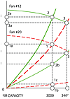
FIGURE 2. Curves of vent systems, fans, and fan outlet velocity pressures.
CONFUSION
A great deal of confusion exists in engineering literature regarding the use of static pressure. The difference in terminology and nature of the SPs and Fs is clearly illustrated in Figures 1 and 1a.SPs = SPo-SPi7,9 Fs = Ft - Fvpo9,10 Since neither SPs nor Fs represent the amount of energy which must be imparted to the system by the properly selected fan, these two values are absolutely irrelevant as a basis for the fan selection.

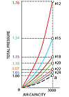
FIGURE 3. Vent system curves of the different fans.
However, there is apparent contradiction even in the ASHRAE handbook, such as: "System resistance to air flow is noted by total pressure ... To obtain the fan static pressure requirement for fan selection where the fan total pressure is known, use: Ps = Pt - Pv,o".8
Now, the following questions must be solved:
As described in the ASHRAE handbook, the following is a procedure for the fan selection8:

TABLE 1. The NYB catalog data for fan 20 PLR. (Table courtesy of New York Blower Co., Bulletin 051.)
In the first case, a designer selects fan size of 20 PLR. In the second case, a contractor selects the least expensive fan size of 12 PLR (Table 2). In both instances, it appears that both fans have the same cfm and Fs, however, there is a noticeable difference in Ft pressure between the two options.
Figure 2 is provided to illustrate the results:
Fan 20 PLR, 3,000 cfm at Fs =1 in. wg; 1,000 rpm:
Fan 12 PLR, 3,000 cfm at Fs=1 in. wg; 3,200 rpm:
Fan 12 PLR, 3,400 cfm at Fs=1 in. wg; 3,200 rpm:

TABLE 2. The NYB catalog data for fan 12 PLR. (Table courtesy of New York Blower Co., Bulletin 051.)
Table 3 lists fans, which were selected from fan manufacturer's data, for an air capacity 3,000 cfm at 1 in. wg Fs (Point "a").
Figure 3 shows that each of the selected fans has a different curve for its particular individual system as compared to the designed vent system. The parabola 0-a, is the imaginary characteristic line of the designed vent system with 3,000 cfm at 1 in. wg Fs.
Key Point 2. The artificially determined value of Fs, while neglecting the Fvpo, cannot be produced by a fan as a single value. In reality, the fan imparts in a vent system the Ft.
Therefore, in spite of having the equal Fs and air capacity, the different fans (Table 3, Figure 3) have different Ft. Figure 3 illustrates that when a selection of fan is based on Fs, neither one of the fans satisfies the designed vent system.

TABLE 3. The NYB catalog data for different sizes of Fans. (Table courtesy of New York Blower Co., Bulletin 051.)
