There is some dispute in the engineering community about the causes and cures of temperature change. This article examines temperature change at four of the air-handling units (ahu's) serving the Indiana University Chemistry Building and how the problem was addressed.

Pump power = 140-hp pumps, constant speed.
Control valve differential = Varies from 10 to 50 ft.
Supply water temperature = Rises as load decreases, 42° up to 55°F.
Dehumidification of critical spaces = Inconsistent.
Chilled-water temperature change = At design.
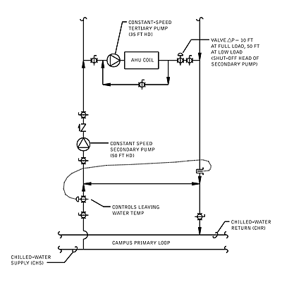
Figure 1: The as-designed chilled-water system for the Chemistry Building at Indiana University.
Crystal Clear Problem
The Chemistry Building at IU's Bloomington campus is home of many of the university's chemistry research facilities, including the Molecular Structure Center, internationally renowned for the study of crystallography. Because of the nature of much of the research, the building's labs need precise control of temperature, humidity, and space pressurization.As designed during 1998 renovations, 16 80,000-cfm variable air volume (vav) primary air handlers serve IU's Chemistry Building. Ten run with 100% outside air, and the other six are conventional vav units. AHU volume is controlled by the static pressure in the corridors outside the research labs, which is maintained at 0.02 to 0.05 in. wc above the labs. Most of the labs run at a slight negative pressure due to fume hood and general exhaust fans.
Because of the nature of the experiments, labs run 24 hrs a day, seven days a week. The ahu's maintain a constant 55°F discharge, using chilled water from IU's central chilled-water plant for the cooling medium. The chemistry department has found that AHU leaving air temperatures in excess of 55° may result in high space humidity, and has a significant detrimental affect on the growth of the molecular crystals. Space temperature is controlled by hot water reheat at each of the vav terminal units.
IU maintains summertime chilled-water supply temperature of 42°F in the campus primary loop, with a design return temperature of 55°.
The schematic in Figure 1 is similar to ASHRAE Systems Handbook, Chapter 11, Figure 4E, where the secondary and tertiary pumps are constant-speed units and the building control valve maintains leaving water temperature at design, namely 55°F. This arrangement had 140 hp of constant-speed pumps serving the four ahu's in this study. The ahu control valve differential pressure varies from 10 ft (design) at full load, up to the shutoff head of the secondary pumps (50 ft) at low load. This arrangement varies the chilled-water supply (CHS) temperature to the coil.
At full load, CHS will be 42°; at low loads it is allowed to rise to 55°. Because of this variation in CHS, dehumidification of the primary air was inconsistent, which was an unacceptable condition for the labs.
To solve the inconsistent dehumidification problems, this system was modified in 1992. This change deleted the leaving water temperature control, installed a check valve in the secondary loop decoupler (to prevent CHS from bypassing directly to the return line), and converted the coil tertiary pump to intermittent operation. The new configuration, shown in Figure 2, solved the dehumidification problems.
In this arrangement, the coil pumps ran only at low-load conditions to keep the water side of the coils from reverting to laminar flow, and also during winter to provide some protection against freezing. Pump horsepower was decreased from 140 to 60 hp, but control valve differential pressure increased dramatically at low loads, up to as much as 100 ft (primary loop differential plus secondary pump shutoff head). This exceeded the valve close-off rating, and several of the valve operators had to be upgraded.
Theoretically, when a cooling coil operates at reduced load, the chilled-water ?T should go up. As the water flow through the coil decreases, the leaving water temperature should more closely approach the coil entering air temperature. At IU's Chemistry Building (and probably many more places), the chilled-water ?T went down rather than up at reduced loads. This is classic "Low ?T Syndrome." Several possible causes were looked at, but the most glaring culprit was the control valve.

Pump power = 60 hp, constant speed.
Control valve differential = 10 to 100 ft.
Supply water temperature = 42°F constant.
Dehumidification of critical spaces = Good.
Chilled-water temperature change = Below design.
Figure 2: IU Chemistry Building's chilled-water system, as modified in 1992.
Keep An Eye On Pressure Drop
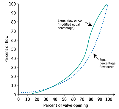
The control valve used at each of these air handlers is a butterfly valve with a pneumatic actuator. This particular style is not listed in the1996 ASHRAE Systems and Equipment Handbook (Chapter 41.7) discussion of valve flow characteristics, except that "their use is limited to applications where their flow characteristics suffice." ASHRAE does show valve characteristics for quick-opening, linear, and equal-percentage porting.The valve manufacturer has listed the characteristics of this valve as "modified equal percentage" (Figure 3). While a butterfly is a quarter-turn valve, it performs differently than a standard, quick-opening valve. The modified equal-percentage operation is limited to 70% maximum open by the valve actuator, and it is closed at 15% of valve stroke. Over this range, the curve very closely approximates ASHRAE's graph of an equal-percentage operation.
Figure 3 shows how the valves react when the differential across the valve is constant. However, the pressure drop is not constant. It varies from a minimum pressure when the valve is wide open, to maximum when the valve is at the low end of its control range. The ratio of these two pressures is called the "valve authority."
In the Figure 2 scenario, the valve authority was 10 ft divided by 100 ft, or 0.10. Figure 19 from Chapter 41.8 of the 1996 ASHRAE Systems and Equipment Handbook shows the valve authority impact on valve characteristics. Again quoting ASHRAE: "If the maximum pressure drop across the valve is more than five times the design pressure drop at max flow, controllability is compromised."

A Chilled-Water Event
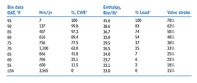
The university describes the need for cooling as a "chilled-water event." In IU's Chemistry Building, the ahu's operate on 100% outside air, and they are programmed to discharge 55° air all the time. Therefore, a chilled-water event occurs whenever the outside air is above 55°. In the 100% outside air scenario, the only load on the cooling coil is outside air enthalpy.Table 1 shows weather data for Bloomington, the hours at each range, corresponding coil load, valve position at each point, and cumulative percent of time at that or a lower load. As shown, the control valve was operating almost all the time at a very small percent open. The chart shows that the building operates 80% of the time with the valve operating in the bottom 20% of its control range.
No wonder temperature change is a problem, since a minor change in valve position could lower leaving water temperature by several degrees. The amazing thing is that it worked as well as it did.

Pump power = 20 hp (average estimate).
Control valve differential = 34 ft at minimum load to 10 ft at full load.
Secondary supply temperature = 42°F constant.
Dehumidification of critical spaces = Good.
Chilled-water temperature change = Improved.
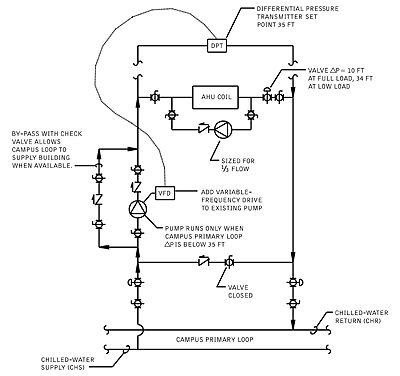
Figure 4: The chilled-water system in its newer, variable-speed configuration.
Going Beyond Tradition
The schematic in Figure 4 shows how the system was modified to convert the building's secondary pump to a "traditional" variable-speed approach. A pump bypass loop was installed with a check valve; the coil tertiary pumps were relocated to a recirculation position; and a differential pressure transmitter (DPT) was added to the end of each loop. The DPT monitors pressure at the end of the main and speeds up or slows down the secondary pumps as required.A constant differential is maintained across the most remote coil, independent of the load on the system. At IU's Chemistry Building, the differential was 35 ft. The control valve will see differential from 10 ft at full load, up to 33 or 34 ft at low load.
This is a significant decrease in the maximum valve differential. The valve authority went from 0.1 in the as-modified scheme, to 0.35 in this scheme. The Virtual Valve configuration takes this one step further. Pump laws state that as flow changes, head pressure changes as a square of the flow. For example, at full load, an AHU in the building will need 35 ft of chilled-water differential to move water through the piping, coil, and control valve. At half flow, the pressure drop through the same piping, coil, and valve will be 0.5 x 0.5, or 0.25 of 35 ft (8.75 ft).
Normally the control valve must absorb the difference (an additional 26 ft in this case). But by resetting the differential setpoint as a function of outside air temperature, the Virtual Valve can absorb the excess head, allowing the control valve differential to remain relatively constant over the entire range of cooling loads. The valve authority is now at or above 1.0, and the range of the valve is much wider.

2Cumulative chilled-water event (the percent of cooling hours in a year that chilled water is required at that load or less). Total cooling hours per year is 5,195.
3Outside air (OA) enthalpy, Btu/lb, based on an average relative humidity of 50%. On 100% OA units, the only load is OA enthalpy.
Table 1: Bloomington IN temperature information and corresponding system data.
Easier On The Pump (And Pocket)
The results at IU have been very encouraging. According to Doug Trueblood, IU's environmental controls coordinator, they've seen a big improvement in their temperature change with no problems maintaining ahu discharge air temperature. A spot check on a recent hot summer day showed the chilled-water temperature change at 16°, a remarkable improvement from the 8° or 9° the building had been experiencing (design temperature change is 13°).Trueblood said that they are using the same sequence in several other locations with similar success, and projects are in the works to convert the balance of the Chemistry Building to the Virtual Valve. "I know we're saving a lot of money," he said. "The building pumps hardly ever run."
From the original design, 140 hp worth of pumps has been dumped from the system. Recognizing that these pumps ran more than 5,000 hrs a year, the utility bill has been decreased by $20,000 annually.
At IU's Chemistry Building, the only variable on the ahu load was outside air. In this case, the use of a reset schedule based on outside air temperature worked out well. It is not the best process variable to control from; outside air wetbulb would have more accurately reflected the load on the units. However, outside air temperature was chosen for this application because it is easy to track, easy to maintain, and "close enough."
On systems with more conventional load profiles (i.e., with a large internal load component) the Virtual Valve should be controlled by a feedback signal from the control valves. Such a sequence would call for a setpoint that keeps at least one valve almost completely open. ES
