Marshalltown Medical and Surgical Center (Marshalltown, IA) is a hospital facility that has provided medical service to the Marshall County area for almost 100 yrs and has developed into a medical center covering over 250,000 sq ft. This facility has seen numerous expansions over the last 100 yrs and has had several different approaches to addressing the mechanical system modifications that were required to facilitate the added services and square footage. Some of the original equipment used in these mechanical system expansions have become outdated and give opportunity for significant energy savings through engineering analysis and system upgrades.
A preliminary energy study under the direction of the mechanical management company Aramark was completed in the fall of 1997. This study identified several energy intensive processes that could be addressed for energy savings. Following development of this study, initial budget estimates were determined and a plan for energy-saving improvements was outlined. Additional engineering and design was required to develop and detail the plans.
This particular project initially focused on the replacement of the chilled water plant, originally installed in 1962. The project later addressed the expansion of the chilled water system in place of inefficient air-cooled refrigeration units installed in a 1976 addition. This addition, a four-story complex plus basement, includes patient rooms, pediatrics, a new lobby, and a complete kitchen/cafeteria.
Original Mechanical System
The original chilled water plant included reciprocating compressors and air-cooled condensers contained within three separate chiller units with a total cooling capacity, when fully operational, of approximately 280 tons. The chilled water plant served portions of the facility and was supplemented by separate air-cooled refrigeration units in several areas.
The 1976 addition included multiple roof-mounted, air-cooled refrigeration units ranging in size from 10 to 15 tons connected directly to refrigeration coils in individual air-handling units (AHUs). The original mechanical design provided three vertical mechanical room shafts that extend from the first to the fourth floor. These vertical shafts housed the AHUs that served each floor. The second through fourth floors utilized three AHUs on each floor, each providing heating, cooling, and ventilation. The basement and first floor utilized multiple units for the diverse usage incorporated into these areas. Above each of these shafts was a penthouse containing exhaust equipment and outside air intakes that utilized vertical ducts to provide air exchange to the facility. The number of cooling units on the roof added up to 16 separate units and approximately 250 tons of cooling.
Project Development
A joint design-build team including, VGI Design (Des Moines, IA) and Wolin and Associates, LLC, were chosen to engineer and install the chilled water plant and retrofit the existing 1976 addition. Both firms have experience with chilled water retrofits, an understanding of the hospital's daily operations, and the ability to efficiently complete the project within the constraints required.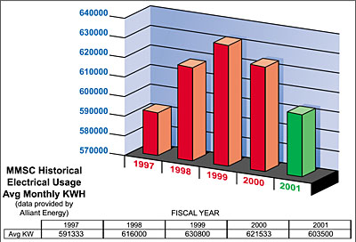
Phase I
The initial phase of the project was quickly brought to action following a failure of two out of the three chillers in early spring of 1998. It was determined that the operational chiller had to remain in place temporarily for spring cooling. A new chiller would then be set in place of the two failed chillers. This key decision allowed for a smooth transition but also required a quick turnaround since the remaining original chiller had limited capacity and the reliability of this unit was highly questionable.Chiller Selection
The lowest initial cost option would be to select air-cooled chillers again. This selection however, would be the most energy intensive, so other options were researched. Noise levels were a major concern of the hospital staff and engineers, since critical laboratory areas are in close proximity to the mechanical room housing the chiller plant. A screw chiller option was eliminated due to the added costs that would be required for noise dampening requirements. The high efficiency and the reliability factors of water-cooled centrifugal chillers along with low noise levels were reviewed and decided as the best selection based on the design criteria. A custom rebate was offered by the local electric utility to assist with the added costs of the high-efficiency centrifugal chillers. The chiller capacity was selected based on existing design day loads plus future cooling retrofits and expansion that would be required in future phases.The limited space for the new chiller required detailed coordination between engineer and tradesman to be sure there were no "surprises" when the chiller, pumps, and piping were installed. All the modifications were completed and only one eight-hr shutdown was required to bring the new system back on-line. Careful planning and close interaction between all the team players allowed future taps and valving for the next phase to be incorporated and prevented the need for an additional lengthy shutdown.
The initial phase of the chiller project was completed successfully in early summer of 1998 and included a 450-ton high-efficiency centrifugal chiller, two 400-ton cooling towers, and a primary/secondary pumping system including variable-frequency drives (vfd's), all under the control of the networked direct digital control (ddc) system installed in the facility.
Phase II
The second phase of the project included the installation of a second 250-ton chiller in parallel to allow for efficient partial-load operation and redundancy for the Phase I chiller plant. This phase was completed easily during the winter of 1999 due to the planning completed during the first phase. The chillers are automatically staged by monitoring chilled water differential temperature and motor amp draw to accurately determine when additional cooling capacity is required or if the smaller 250-ton unit more closely matches the actual cooling load.The new chiller system is able to provide chilled water at a fraction of the cost of the original chiller units with a power usage of 0.54 kW/ton for the new chillers compared to the original equipment producing at 1.4 kW/ton. Due to the age of the original equipment (installed in 1962) and the high level of reliability of the new equipment, this retrofit also significantly reduced the amount of unexpected and costly service calls and repairs.
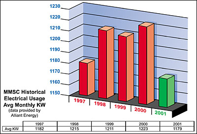
The cost savings along with the one-time rebate from the power utility company amounts to an initial one-time rebate to the owner of $20,000 and an annual savings of approximately $12,000. Some of this estimated cost savings must be reduced due to improved cooling performance. For example, additional dehumidification occurs with a constant 42?F chilled water production compared with the fluctuating chilled water temperature and finite on-off steps of the direct exchange (DX) systems that were originally used. The utility company has provided a monthly monitoring of power consumption to track the actual savings (Figures 1 through 3).
Phase III
The third phase of the project included the expansion of the chilled water usage to include the 1976 addition. The originally installed cooling system for this addition utilized several air-cooled refrigeration units connected to individual AHUs. The total capacity of these units was in excess of 250 tons and operated at an estimated 1.50 kW/ton compared to the 0.54 kW/ton provided by the new centrifugal chiller plant. The existing installation also utilized R-22 refrigerant, which has increasingly limited availability and required significant maintenance as the system aged, to prevent compressor failure and refrigerant loss.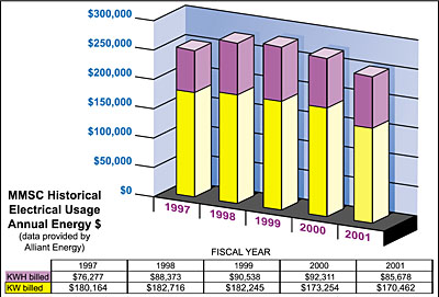
Coil Selection and Distribution
The final engineering required for the project included the replacement of the refrigeration coil in 16 separate AHUs with a chilled water coil and distribution piping to each mechanical room.Sizing of the new cooling coils was balanced with cooling output due to the limited space in the existing AHUs and limited fan static pressure capacity. Final coil selection was optimized at 42? chilled water with a 10? rise to minimize air pressure drop while still providing the required cooling capacity. The sizing and routing of the chilled water loop started at the chiller plant and distributed to all the new coils. The system has been engineered to provide variable-flow water distribution and also expandability for additional cooling conversions as budgets allow.
Pipe routing was kept within the building envelope to eliminate the need for freeze protection. A variable-speed pumping system was incorporated along with two-way control valves on each chilled water coil to allow flow diversity.
Additional Discoveries
During preliminary design development an additional requirement was discovered. The original installation did not provide adequate outdoor air to provide free cooling to the 1976 building. This area has a significant internal load, allowing several hours of free cooling during lower ambient temperatures. Without this free cooling, extended refrigeration compressor operation was required, consuming excess energy and significant compulsory maintenance for winter compressor operation.The original design utilized a vertical outdoor duct with each of the air handlers required to pull air from a vertical airshaft for ventilation with the intake located at the penthouse. The airshafts are incorporated into the building and could not be enlarged to allow for added outdoor air. The units farthest away from the intake received limited outdoor air and had the largest free cooling requirements since the first floor and basement housed several heat-producing operations. It was also discovered that the original pneumatic control system was also installed or modified to provide only minimum economizer operation.
Additional requirements incorporated into the design to provide free-cooling operation included:
- Outdoor air intakes at each penthouse were outfitted with roof-mounted fan utility sets to increase the airflow levels to allow free cooling during spring and fall conditions.
- Relief and exhaust fans were also replaced or sped up, as needed, to relieve the building under free cooling operation. And
- Control components were added to modulate the outdoor air fan operation between minimum outdoor air and full free cooling and provide full economizer operation under the proper ambient conditions.
Additional improvements to the facility included a positive building pressure for all areas except the kitchen, and improved airflow at each air handler due to increased inlet pressure at each supply fan.
New Technologies
To assist with the daily communications, a new technology was used in the form of a project extranet developed and maintained by VGI Design and utilized by all team players to perform design development and construction oversight. The extranet allowed for quick communication during problem-solving situations and information transfer between all team players. The project extranet also allowed for more interaction and input from the facility manager, Rex Shotkoski, who was responsible for interfacing with the hospital staff, engineering team, and contractors during the construction phase.All team members accessed the project extranet by use of a login password system. It also was used as a single depository for the daily construction communication that occurred as the job progressed. This eliminated the need for a paper file to constantly be maintained or concern for lost correspondences that occur via independent e-mails and faxes. The project extranet also required all team players to be accountable for timely response to each other since it distributed communications to all selected persons involved and tracked time for a response to be completed and distributed.
Lastly, the project extranet was used as an electronic filing cabinet for all the critical communications, submittals, and construction documents. The extranet, upon completion of the project, was archived to a compact disk that could be used for closeout documentation and turned over to facility maintenance personnel.
Final Project Modifications
Updating and modification of the control systems to provide fully modulating economizer dampers and chilled water valve control was also needed. The design team decided to use a hybrid control system that utilized the existing pneumatic controls to modulate dampers and the control valve, and a new digital control system to provide a networked monitoring system of all the modified air handlers.The project was completed and was so successful that the replacement of two additional rooftop units was also completed for the laundry department. This included a complete AHU designed with chilled water cooling and free cooling for this internal heat load area. This phase translated into cost reductions in the form of energy savings as well as an elimination of refrigeration service and repair for multiple units. The estimated cost savings amounts to an annual savings of approximately $10,000.
The third phase of the chilled water retrofit was completed in August of 2000 with ddc control commissioning to verify operation. A close monitoring of energy usage by maintenance personnel and the local utility company is underway to verify the energy reductions that have been estimated. Monthly electrical usage reports have shown a reduction in usage compared to last year. Continuous monitoring is in practice to get a full two years of energy data to compare to the estimated savings.
Project Summary
The Marshalltown Medical and Surgical Center was able to replace outdated, unreliable chillers and reduce energy usage significantly within the chilled water plant through a design-build team that included the engineering services of VGI Design and contracting from Wolin and Associates LLC. Additional work included expanding the use of chilled water in place of air-cooled refrigeration, further reducing energy and maintenance costs. As a side project, the amount of free cooling hours was significantly increased over original operations and provides additional energy savings. To assist with the daily communications, a new technology, in the form of a project website developed and maintained by VGI Design, was utilized by all team players to perform design development and construction oversight.The project was completed in August of 2000, when ddc controls and the commissioning process were finalized. The estimated annual energy savings from a new chilled water plant; elimination of small, inefficient cooling units; and free cooling is estimated to be approximately $12,000/yr. The estimated reduction in maintenance cost, through elimination of numerous compressor replacements, refrigeration loss, and electrical repairs, was estimated to exceed, on average, an additional $12,000/yr. Some of this estimated cost savings must be reduced due to improved cooling performance. Monitoring of energy usage by maintenance personnel and the local utility company is underway to verify the estimated energy reductions. ES
