
The Bypass Pipe’s Balancing Valve: Part II, Case Studies
In August’s column, I discussed three-way control valves, their associated bypass pipes, and the importance of a balancing valve being located within the bypass pipe. Such balancing valves are needed to throttle flow. If missing, or left wide open, excessive flow can be sent through the bypass during periods when the three-way control valve is directing some flow towards the bypass. Such excessive flow can create numerous second-order effects that can devastate the proper operation of the hydronic system. August’s column laid out the fundamentals of when three-way control valves are needed, provided detailed explanations of the effects an unthrottled balancing valve in the bypass can have on a system, outlined how to appropriately determine bypass flow rates for setting of the balancing valve, and described how commissioning engineers can break the cycle of neglect this industry has put on the bypass pipe’s balancing valve. This article seeks to provide greater context through several case studies to demonstrate just how bad these second-order effects can get.
Case Study 1: System Instability
Part I provided an explanation of how a three-way control valve serving an AHU’s coil may be susceptible to poor temperature control due to an unthrottled bypass balancing valve. Excessive hunting around discharge air temperature setpoint may be realized. The control instability that can come from unthrottled bypass flow does not always remain localized, however.
Our firm recently worked with a building which required chilled water system operation late into the fall. Their water-cooled chiller kept tripping off during such colder outdoor air temperatures. At times, the chiller was cycled back on and other times it would lock itself out. We identified the root cause was a missing balancing valve in the tower bypass line. A modulating three-way control valve was used to modulate the amount flow going to the tower and through the bypass, as to keep the condenser water supply temperature at a minimum setpoint of 60°F. Such a balancing valve is needed and should be set to have a pressure drop equal to the height of the tower1.
Without the bypass’s balancing valve, nearly all the water would immediately go through the bypass the moment the valve began to modulate open the port to the bypass pipe. This short circuit of water quickly resulted in climbing condenser water supply temperatures. Sometimes, the chiller would trip out on excessive surge before the control valve could modulate flow back to the tower. Other times, the chillers would ramp up to overcome the additional refrigerant lift and avoid tripping out on surge, then the bypass valve would fully open to the tower and slug of cold condenser water from the cooling tower would hit the chiller. The chiller could not ramp down quick enough and would cycle itself off when the chilled water supply temperature dropped several degrees below setpoint.
Installing a balancing valve in the bypass was not possible due to space limitations. The control loop gains were reduced to slow down the modulating three-way control valve. Additionally, the setpoint of the cooling tower basin heaters was raised to mitigate how cold that water could get. Such improvements have thus far seemed to curb the instability.
Case Study 2: Staving Adjacent Loads
Like the chiller example above, the second-order effects of missing the bypass pipe’s balancing valve often are realized elsewhere in the system. Operating rooms in a hospital generally have very high airflows coming through their supply-air VAV boxes, and this almost always results in the air needing to be warmed by use of a reheat coil to prevent overcooling the space. I recently was testing a set of operating rooms, all served by three-way control valves at their supply-air VAVs. All operating rooms were initially able to maintain space temperature just fine. Then one of the operating rooms was placed into an unoccupied mode of operation, which reduced its supply airflow and in turn the load on the reheat coil. Its three-way control valve opened more to the bypass, which had a balancing valve that had been left wide open. Excessive flow went through that bypass pipe, stealing flow from adjacent ORs, several of which lost their ability to provide appropriate temperature control. Two of the ORs settled out nearly 6°F below their space heating setpoint. This issue was solved when the testing and balancing (TAB) professional was brought back to appropriately set the balancing valves in the bypass pipes.
This case study highlights just how unintuitive the second-order effects of unthrottled bypass flow can have; all the operating rooms were able to meet space temperature requirements at full load, but the moment a single space had a reduction in load, adjacent spaces were unable to be adequately heated.
Case Study 3: Unexpected Return Water Temperatures
Unthrottled flow through the bypass will raise the temperature of the return water in heating hot water system. A new hospital our firm worked on included a heat recovery chiller that extracted heat out of the chilled water system and expelled it into the heating hot water return piping. A simplified piping diagram of the system is provided in Figure 1. This heat recovery chiller was to be the only source of cooling in the winter. However, higher-than-designed-for hot water return temperatures were being experienced, and the heat recovery chiller was often tripping out due to the excessive lift it had to overcome (i.e., it could not expel the heat to the hotter-than-expected hot water return piping). It was discovered during functional testing that the balancer had not set any of the balancing valves at the various three-way control valves out in the system. The designer was informed, and he provided direction to balance all such valves to ¼ of their associated VAV box’s scheduled flow rate. These three-way control valves were merely for ensuring hot water was available “on-demand” at several critical loads, as the hot water plant already had a dedicated low flow bypass valve to ensure minimum flow requirements of the boiler and pump were met. The team reported seeing an 8°F drop in hot water return temperature immediately following the rebalancing effort, improving the stability of the heat recovery chiller operation.

Case Study 4: Excessive Velocities
Excessive velocities may be experienced through an unthrottled bypass. In a recent project, the cooling tower bypass pipe shown in Figure 2 did not have a balancing valve. The three-way control valve was configured for two-position control (either all the flow goes to the tower, or all the flow goes to the remote sump). TAB measurements confirmed system flow was much higher when going through the bypass.

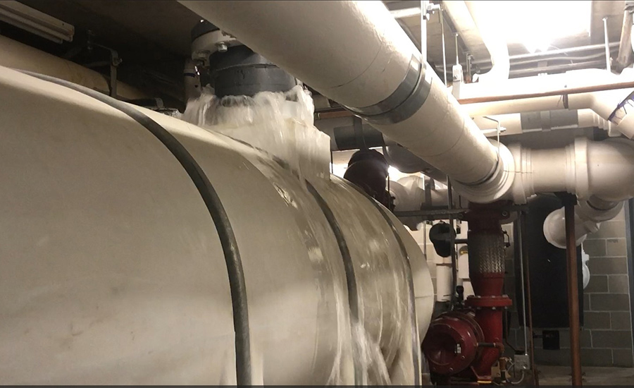
This excess flow through the bypass would enter the remote sump at such a velocity that water would violently splash out at the unfastened connection at the top of the sump, see Figure 3. Each time the condenser water temperature dropped low enough to initiate the three-way control valve to direct flow to the bypass, a substantial amount of water would flood the mechanical room. During my initial investigation, water levels in the mechanical room rose so much I had to leave out of fear of electrocution.
In lieu of retrofitting the bypass with a balancing valve, we implemented control logic which slowed the pump down when the three-way control valve directed flow to the bypass. This was possible as the condenser water pumps were served by variable speed drives. We dubbed this solution a “software balancing valve.” We also lowered the water level setpoint on the remote sump for the makeup water valve to mitigate any spillover going forward.
Case Study 5: Excessive Noise
On a recent retrofit project in an existing hospital, we heard noise complaints from occupants. Investigation into the VAV box located above their ceiling found the bypass pipe had no balancing valve. It did, however, have an isolation valve, which we used to throttle flow and eliminate the noise complaints.
Case Study 6: Pump Staging Instability And Energy Waste
The intent of variable speed pumping systems is for the pumps to slow down and save energy as the thermal load on the system is decreased. I was on a project a few years back for a new heating hot water system serving only two large air-handler unit coils, one of which had a three-way control valve to ensure minimum flow through the systems is maintained. The pumps were sized for lead/lag, meaning during low load situations, only one of the pumps should be running2. Prior to testing, the controls programmer called and stated that though he had correctly programmed the lead/lag sequence, only one pump was running in the winter months, but as spring came the lag pump enabled and they both ramped for full speed, unable to maintain the differential pressure setpoint. I then called the balancer to ask what flow he set the bypass’s balancing valve to. He stated the valve was not installed, despite being shown in the drawings. The differential pressure sensor used for pump control was also located very close to the three-way control valve. As the load on that coil reduced, water was directed into the bypass, and the system differential pressure dropped (instead of rising). Thus, the lead pump sped up trying to maintain setpoint. The lag pump eventually enabled as well, and they both got stuck at full speed.
This issue was communicated with the construction team. The balancing valve was installed and set, and the differential pressure sensor was moved further away from the three-way control valve, and the system operation began regained stability.
Conclusion
As stated in Part I of this series, there is a severe indifference throughout this industry as to the criticality of the bypass pipe’s balancing valve. In the case studies presented, unthrottled flow through the bypass pipe was a root cause of many drastically different issues that these buildings were experiencing. The six case studies were from projects I was personally involved with in just the last three years. Think of how many other buildings out there are hurting just the same!
I hope readers are now armed with better understanding of these balancing valves, a greater appreciation for their criticality, and some more skills to effectively troubleshoot the very nuanced problems we often encounter as commissioning providers.
References:
1Energy Design Resources. 1999. CoolTools Chilled Water Plant Design Guide.
2Ryan, M. 2023. “Commissioning Lead/Lag Pumping Operations: Part I, Identifying a Designer’s Intent.” Engineered Systems Magazine (January).


