
Beyond the wheel, the most important mechanical equipment serving humanity is the centrifugal pump. Centrifugal pumps make modern quality of life possible. Turn on a faucet and a centrifugal turbine pump provides the water. Do you have a dishwasher, clothes washer, or sump pump at home? Each of these employ centrifugal pumps. It’s important to select the best pump control method to provide a properly operating, energy-efficient, and reliable pumping system.
Centrifugal pumps have two modes of operation: constant flow and variable flow; however, there are several control methods to achieve these two modes of operations, each with specific advantages and disadvantages. The specific technical information needed to evaluate different pump control methods for specific applications will be discussed, followed by several pump application examples.
The analysis to select a pump control method for a particular application requires knowing the anticipated pump operating parameters, being familiar with the different pump control methods with their advantages/disadvantages, knowing how pumps perform under each control method, and understanding the applicable codes and standards that may dictate a specific pump control method.
1. Determine Pump Operating Parameters
Determine the pump operating conditions.
a. What type of mechanical system is the pump serving? Common system types include circulating water within a closed system for heat exchange, removing or adding water to a tank/process, or pressurizing water for distribution (fire pump, domestic water distribution).
b. What variable is the pump operation trying to control? Typical controlled variables are system pressure differential, system supply pressure, system flow rate, fluid level maintenance, and/or fluid level reduction.
c. What is the system’s anticipated operating pressure? This is a combination of static head and friction head.
d. Is the hydronic system open or closed? If it’s an open system, what is the static head the pump has to overcome? If it’s an open system, what is the net positive suction head (NPSH) for the pump?
e. What are the system’s flow requirements? Constant flow rate versus variable flow rate. If variable, what is the anticipated flow operating range?
f. What are the system’s anticipated hours of operation? Is it continuous, infrequent, or seasonal?
g. Is the hydronic system fluid 100% water or is it a water/anti-freeze mixture? Anti-freezes have a large impact on fluid heat-transfer capacity and system pressure differential requirements.
h. What is the normal operating temperature range? The operating range for chilled water is typically 40º-60ºF. The operating range for heating water is typically 120º-180º. The operating range for steam condensate is typically 180º-210º.
i. What is the required system reliability? Is it single pump, partial redundancy (e.g., two pumps at 67% capacity), N+1 pumping capability, or dual active N+1 pumping capability?
2. Pump Curves and Pump Curve Performance
As part of determining how to control centrifugal pumps, it’s important to understand the operating characteristics of a centrifugal pump under different control methods. The most prevalent pump control methods include on-off control, two-speed control, throttle valve control, bypass valve control, VFD control, and parallel pump control. The pump operating characteristics, advantages, and disadvantages for each pump control method are as follows:
a. On-Off Control
In the on-off control method, the pump is either off or on with the pump running at a constant speed. Looking at Figure 1, when the pump is off, the only pressure in the hydronic system is the static head (this applies to all control methods). When the pump is on, the hydronic system pressure and flow will follow the system curve until it reaches the pump curve. The hydronic system pressure and flow will only operate where the system curve intersects the pump curve.

> FIGURE 1. A pump with on-off control.
The advantages are:
i. It’s good for open systems that have high static and/or friction head requirements;
ii. It’s good for systems that have constant flow requirements;
iii. The on-off control system is economical; and
iv. It’s good for systems with relatively few hours of operation per year.
The disadvantages are:
i. It cannot provide variable flow;
ii. The motor will draw lock rotor amperage during pump startup;
iii. The pump seals and bearings are exposed to higher stresses and shorter life spans due to hard starts; and
iv. Due to the pump operating at constant speed, its net positive suction head (NPSH) remains the same, and caution needs to be taken in open tanks to ensure the water level does not drop below the required pump NPSH.
b. Two-Speed Control
In the two-speed control method, the pump is either off, low speed, or high speed. Similar to on-off control, the pump will maintain a constant speed at each operating point. Looking at Figure 2, when the pump is in low speed, the hydronic system pressure and flow will follow the system curve until it reaches the low-speed pump curve. When the pump is in high speed, the hydronic system pressure and flow will follow the system curve until it reaches the high-speed pump curve. The hydronic system pressure and flow will only operate where the system curve intersects the specific speed pump curve.
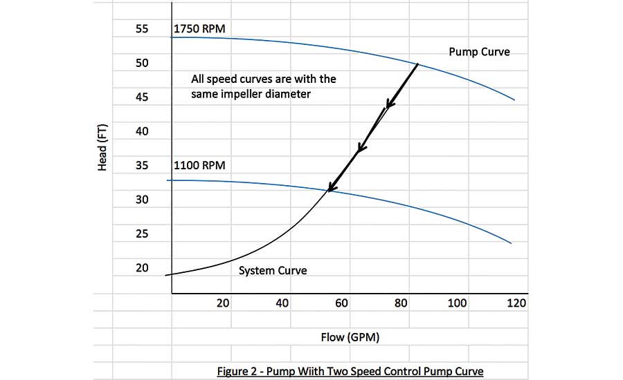
> FIGURE 2. A pump with a two-speed control pump curve.
The advantages are:
i. It’s good for open systems that have high static and/or friction head requirements;
ii. It’s good for systems that have two well-defined flow requirements;
iii. Its two-step control system is economical;
iv. It’s good for systems with lower hours of operation per year; and
v. It’s more energy efficient than the throttle valve and bypass valve control methods described below.
The disadvantages are:
i. It cannot provide variable flow beyond or between the two operating points;
ii. The motor will draw lock rotor amperage during pump startup; and
iii. The pump seals and bearings are exposed to higher stresses and shorter life spans due to hard starts.
c. Throttle Valve Control
In the throttle valve control method, the pump is either off or on, and it’s running at a constant speed. Figure 3 has an illustration of a pump with a throttling valve. The purpose of the throttling valve on the pump discharge is to increase the restriction on the fluid flow. Looking at Figure 4, when the pump is on and the throttling valve is actively modulating to maintain stable terminal pressure differential, the hydronic system operates where the system curve intersects the pump curve. When the throttle valve modulates toward closed, the pump operating point moves along the pump curve to the left and results in a lower flow and higher system pressure.
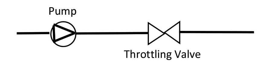
> FIGURE 3. A pump with a throttle valve control.
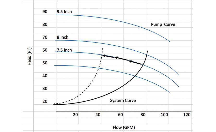
> FIGURE 4. A pump with a throttle valve control pump curve.
The advantages are:
i. It’s good for systems that have stable flow requirements close to 100%;
ii. It’s good for pumps with a flat pump curve; and
iii. The throttle valve control system is economical.
The disadvantages are:
i. The pump discharge pressure can be too high;
ii. Increased system pressure can cause valve cavitation;
iii. The pump seals and bearings are exposed to higher stresses and shorter life spans due to hard starts; and
iv. As the pump operating point moves left on the pump curve, the pump becomes less efficient, resulting in it being less energy efficient.
d. Bypass Valve Control
In the bypass valve control method, the pump is either off or on with the bypass actively modulated to maintain hydronic system required pressure differential. Figure 5 has an illustration of a pump with a bypass valve. Looking at Figure 6, when the pump is on and the bypass valve is closed, the hydronic system operates where the system curve intersects the pump curve. When the pump is on and the bypass valve modulates open, the pump operating point moves to the right along the pump curve resulting in higher flow.

> FIGURE 5. A pump with a throttle valve control pump curve.
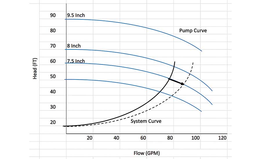
> FIGURE 6. A pump with a throttle valve control pump curve.
The advantages are:
i. Its bypass valve control system is economical for variable flow systems;
ii. It’s good for pumps with a flat pump curve; and
iii. The hydronic system pressure does not increase during partial load conditions.
The disadvantages are:
i. It’s the least energy-efficient pump control method;
ii. The pump seals and bearings are exposed to higher stresses and shorter life spans due to hard starts; and
iii. As the pump operating point moves left on the pump curve, the pump becomes less efficient, resulting in it being less energy efficient.
e. Variable Frequency Drive Control
In the VFD control method, the pump is either off or on with the pump speed modulating to maintain the hydronic system required pressure differential. Figure 7 has an illustration of a pump with a VFD control to maintain a system pressure differential at a remote load. Looking at Figure 8, when the pump is on and the pump speed is modulated, the operating point moves along the system curve to maintain hydronic system pressure differential.
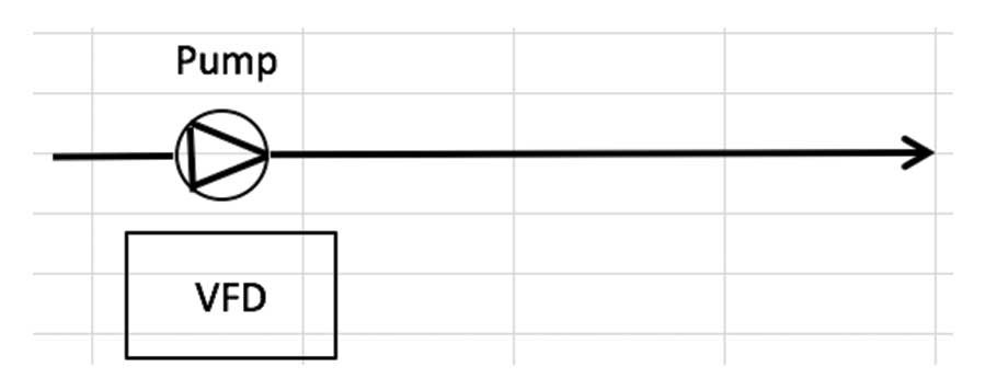
> FIGURE 7. A pump with a VFD control.
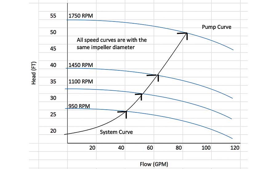
> FIGURE 8. A pump with a VFD control pump curve.
The advantages are:
i. It’s good for systems with high levels of modulation;
ii. It’s among the most energy-efficient pump control methods;
iii. Hydronic system pressure does not increase during partial load conditions;
iv. It offers long bearing and seal life; and
v. It has lower electrical load during soft startup.
The disadvantages are:
i. It has a higher construction cost.
f. Parallel Pump Control
In the parallel pump control method, two or more variable frequency driven pumps are connected in parallel to service the same hydronic system (Figure 9). Looking at Figure 10, when the pump is on and the pump speed is modulated, the operating point moves along the system curve to maintain hydronic system pressure differential. There are several parallel pump control philosophies, which include lead/standby, lead/lag, and parallel operation. Lead/standby has two pumps with one pump operating while the other pump is in standby. If the first pump fails, the standby pump will operate. Lead/lag has two pumps with one designated as lead and the other designated as lag. The lead pump will modulate to maintain system pressure differential. If the lead pump cannot maintain system pressure differential, the lag pump will be activated and operate in parallel with the lead pump. Parallel pumping has two pumps operating at the same time. Both pumps would operate in parallel. When pumps are operating in parallel, it’s important that the pumps are synchronized to operate at the same speed.
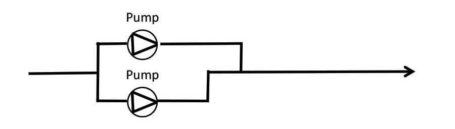
> FIGURE 9. A pump with a VFD control pump curve.
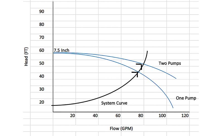
> FIGURE 10. A pump with a VFD control pump curve.
The advantages are:
i. It’s good for systems with high levels of modulation;
ii. It’s among the most energy-efficient pump control methods;
iii. The hydronic system pressure does not increase during partial load conditions;
iv. It has a long bearing and seal life; and
v. It has a lower electrical load due to its soft startups.
The disadvantages are:
i. It features higher construction costs; and
ii. Its controls are substantially more complex.
3. Codes and Standards
Many building codes and standards are increasing energy efficiency requirements for pumped fluid systems that include centrifugal pumps. Three prominent codes and standards that will be discussed are the International Energy Conservation Code, 2018; ASHRAE Standard 90.1-2016; and Code of Federal Registration Title 10, Chapter 11, Subchapter D, Part 431, Subpart Y – Energy Efficiency Program for Pumps. It’s important to research all applicable codes and standards for your specific centrifugal pump application.
a. International Energy Conservation Code, 2018: For comfort conditioning hydronic systems that have a heating or cooling design output capacity equal to or greater than 300,000 Btuh, the hydronic systems shall have the following part-load controls:
i. The supply – water temperature shall be reset based upon building demand and varied based upon coil-valve position, zone-return water temperature, building-return water temperature, or outside-air temperature. The temperature reset shall be no less than 25% of the supply-to-return water temperature difference. (IECC, Section C403.4.4, Item 1);
ii. Automatically vary hydronic system fluid flow for systems having a combined pump motor capacity equal to or greater than 2 hp with three or more modulating control valves. The hydronic system must be capable of having a 50% minimum flow reduction or meet the minimum allowable flow for all connected equipment. (IECC, Section C403.4.4, Item 2);
iii. Hydronic systems serving water-cooled unitary air conditioners are required to have variable-speed drives for motors with nominal power of 2 hp or larger. (IECC, Section C403.4.4, Item 3); and
iv. In open-circuit chiller condenser water systems having variable flow, the condenser water system must be capable of having a 50% minimum flow reduction. (IECC, Section C403.9.4).
b. ASHRAE Standard 90.1-2016:
The following hydronic system energy-efficiency requirements must be met:
i. For heating or cooling hydronic systems that have design output capacity equal to or greater than 300,000 Btuh, the hydronic systems shall have a DDC control system. (ASHRAE 90.1, 6.4.3.10);
ii. For heating or cooling hydronic systems with three or more modulating control valves that modulate as a function of the load, they shall be designed for variable fluid flow. The hydronic system flow will be designed to be reduced to 25% of the maximum system flow rate or minimum required flow rate for equipment (ASHRAE 90.1, 6.5.4.2); and
iii. For heating and cooling hydronic systems utilizing system pressure differential for centrifugal pump control, the pressure differential set point will be reset downward based upon valve positions until one valve is nearly open. (ASHRAE 90.1, 6.5.4.2).
c. Code of Federal Registration Title 10, Chapter 11, Subchapter D, Part 431, Subpart Y – Energy Efficiency Program for Pumps:
The following hydronic system energy-efficiency requirements must be met:
i. The CFR pump standard addresses pump efficiency, which focuses on the pump design and not necessarily on how the pump is controlled;
ii. The standard main method for determining pump energy efficiency is the Pump Energy Index (PEI) with separate formulas for constant flow and variable flow applications; and
iii. The standard will be enacted on Jan. 27, 2020.
The following are three typical centrifugal pump applications, showing how one or more control methods can be applied while meeting the energy conservation codes listed above. The analysis will provide technical constraints for each application and recommended pump control method.
-
Steam system condensate pump — The purpose of the condensate pump is to remove condensate that accumulates in a condensate receiver. The condensate receiver and the tank the condensate is being pumped to are vented, resulting in the condensate system being an open system. The pump condensate flow rate has to minimally meet the condensate flow during steam system warm-up and maximum steam usage. There is no variable flow requirement for condensate pumps. The condensate pump does not need to meet the code and standard requirements. Based upon the condensate pump total head requirement, consisting of static head (elevation difference between receiver and tank) and friction head, the on-off control will provide the necessary total head requirement for removing the condensate.
-
Chiller condenser water pump — The purpose of the chiller condenser-water pump is to circulate water through the chiller condenser and discharge into the top of the cooling tower(s). Depending on the condenser-water system design, there can be a dedicated condenser-water pump for each chiller or a manifold of condenser-water pumps, and a pump can serve any of the system chillers. The cooling tower elevation in relationship to the condenser water sump can have a substantial impact on the required condenser-pump static head. Typically, a chiller condenser-water flow cannot go below 50% of the design flow. For condenser-water systems with high static head, an on-off control or VFD control will provide the flow control.
-
Secondary chilled-water pump — The purpose of the secondary chilled-water pump is to circulate chilled water from the primary chilled water system to the equipment that uses the chilled water for cooling. The secondary chilled water system is a closed system with only friction head requirements. Larger chilled water systems with cooling capacities above 300,000 Btuh typically have many chilled water users with substantial variable chilled water demand. Both the IECC and ASHRAE 90.1 require the secondary chilled water pump to have variable flow. The IECC requires a minimum of 50% chilled water flow reduction, and ASHRAE requires a 75% chilled water flow reduction. Based upon the code and standard chilled water flow reduction requirement, the VFD control and parallel pump control will each provide the proper system flow control.
Conclusions
Each centrifugal pump control method has advantages and disadvantages. It’s critical to have a thorough understanding of the anticipated pump operating conditions, available pump control methods and their advantages/disadvantages, pump operation under each control method, and the codes and standards that affect pump control selection. The proper selection of a pump control method will meet operational requirements and provide long-term energy-efficient, reliable operation.
References
- ASHRAE Standard 90.1 - 2016, Energy Standard for Buildings Except Low-Rise Residential Buildings, Chapter 6 – Heating, Ventilation, and Air Conditioning.
- International Energy Conservation Code – 2018, Section C403 – Building Mechanical Systems.
- Code of Federal Regulations Title 10, Part 431 – Energy Efficiency Program for Certain Commercial and Industrial Equipment, Subpart Y – Pumps.
- U.S. Department of Energy, Hydraulic Institute, Europump; Variable Speed Pumping – A Guide to Successful Applications, Executive Summary, May 2004.
- U.S. Department of Energy, Energy Tips – Optimize Parallel Pumping Systems, October 2006.
- U.S. Department of Energy, Energy Tips – Adjustable Speed Pumping Applications, January 2007.
- U. S. Department of Energy, Energy Tips – Control Strategies for Centrifugal Pumps with Variable Flow Rate Requirements, May 2007.
- Water World, Selecting the Best/Most Efficient Centrifugal Pump Control, Allan R. Burdris, September, 2011.


