
In theory, absorption chillers make an attractive cooling solution because they employ water as an environmentally friendly refrigerant, and they can use heat from a variety of sources to drive the refrigeration cycle instead of costly electricity produced by a utility. In an absorption chiller, the refrigeration effect is the result of chemical and thermodynamic reactions occurring between the water refrigerant and a salt solution, such as a Lithium-Bromide (LiBr) mixture, which drives the refrigeration cycle. Sophisticated controls are required to keep the chemistry in proper balance by regulating pressure, temperature, and concentration (PTC).
For maximum uptime and year-round operational availability, it is essential to optimize the salt-solution chemistry to maintain reliability and minimize impact on efficiency. This challenge has been met by innovative technologies — namely, a 2-step evaporator/absorber (E/A) and a parallel-flow cycle — incorporated in the chiller itself to optimize PTC and enhance reliability and efficiency beyond conventional designs.
Optimizing the chemistry is critical because an absorption chiller's cooling effect is produced by water refrigerant flashing into vapor. The flashing effect occurs in a near vacuum inside the evaporator section as water vapor molecules are pulled into a LiBr solution in the absorber section. To continue the refrigeration cycle, the diluted LiBr solution in the absorber must be pumped to the generator section where heat is used to reconcentrate the LiBr solution. Two types of absorption chillers are employed depending on the available heat source. Single-effect absorption chillers can use low-grade heat sources, such as hot water or low-pressure steam. Double-effect absorption chillers can use higher-grade heat sources, such as medium-pressure steam or the direct firing of natural gas. Because driving heat dramatically affects PTC, it is useful to examine single- and double-effect absorption chillers separately.
The Limitations of Conventional Absorption Chillers
Absorption chillers require PTC to be maintained within a specified range to ensure proper operation. Otherwise, such problems as crystallization and frequent purging can cause substantial downtime. Crystallization is a consequence of a temperature/pressure imbalance in which LiBr and water get separated instead of remaining in solution. Under these conditions, crystals can form and block the internal piping and fluid distribution system, thereby affecting the circulation within the chiller and impacting its performance. The chiller capacity gets reduced until a decrystallization process is performed. Crystallization, as such, does not cause any damage to the chiller or its components. The most common cause of crystallization is loss of control on the cooling water temperature control, which cools the LiBr solution in the absorber below the crystallization point.
Because single-effect chillers operate at lower temperatures and lower LiBr concentrations than double-effect chillers, crystallization is less of a probability. Even so, crystallization is still a concern with single-effect absorption chillers. Dissolving crystals and bringing them back into the liquid state is very laborious and time-consuming.
Until recently, the primary way to minimize crystallization risks was to use controls to prevent the LiBr solution from entering the crystallization zone. Conventional designs rely almost exclusively on controls, but simply relying on controls is often not sufficient to overcome the crystallization issue.
Why Conventional Single-Effect Designs Need Improvement
In a conventional single-effect chiller, there is one evaporator section and one absorber section, and both sections are contained within the lower shell of the chiller (Figure 1). The chilled water inside the evaporator tubes is cooled by the refrigerant water that is distributed over the top of the evaporator tubes. As the refrigerant water evaporates, the water vapor is absorbed by the LiBr solution distributed over the top of the absorber tubes.
Inside the conventional single-effect shell, the absorption process creates a constant pressure (vacuum) level, typically at 7 mm Hg abs. The constant vacuum level has a limitation. As LiBr solution trickles down from the top to the bottom in the absorber section, the rate of refrigerant water vapor absorbed by the LiBr drops. The conventional design works with relatively higher LiBr salt concentrations and has difficulty working with lower concentrations. Consequently, the solution in the bottom section of the absorber is much less effective in absorbing the refrigerant vapor from the evaporator.
Improvements Obtained With A 2-Step Evaporator/Absorber
The above limitation is overcome by splitting the evaporator as well as the absorber into lower and upper sections (Figure 1). The split design creates two different pressure levels within the lower shell, creating a quadrant configuration. A pressure difference between the lower (8 mm Hg) and the upper (7 mm Hg) sections of the evaporator and absorber is created by simply holding the refrigerant water in the liquid distribution trays installed between the upper and lower sections.
The chilled water flows through the tubes in series through the two evaporator sections, while the concentrated LiBr solution is distributed in the absorber shell side in the opposite direction. This enhances absorption of the refrigerant into the LiBr solution, reducing solution concentrations and overall pressure and temperature.
 FIGURE 1. Schematic diagram comparing conventional evaporator/absorber design with 2-step E/A quadrant.
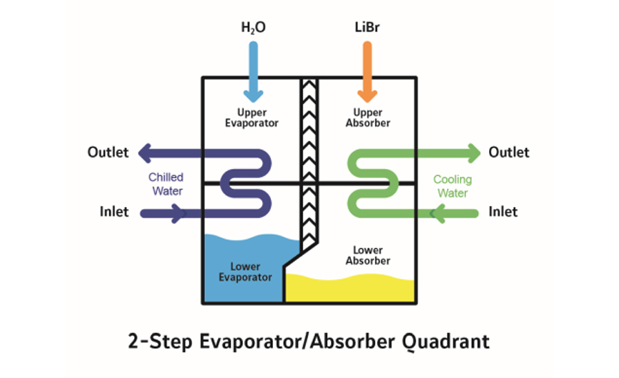 FIGURE 1. Schematic diagram comparing conventional evaporator/absorber design with 2-step E/A quadrant.
Two benefits result from a 2-step design: 1) Absorption is enhanced and crystallization is minimized due to lower percent salt content in the solution compared to the conventional cycle; and 2) Dividing or distributing the cooling load and the absorption process into two steps (two parts) saves significant amounts of pump and input energy.
Here's how the 2-step design works:
1) The solution entering the upper absorber section has a relatively higher concentration than the solution entering the lower absorber section. Thus, the vapor pressure of the solution entering the upper absorber section is lower, thereby providing the necessary vacuum to achieve the desired leaving chilled water temperature (typically 7ºC or 44.6ºF) from the upper evaporator section.
2) The warmer chilled water first enters the lower evaporator section, which results in a higher evaporator pressure and helps to compensate for the higher vapor pressure exerted by the somewhat diluted solution leaving the upper absorber section and entering the lower absorber section. In the lower absorber section, the higher vapor pressure of the LiBr solution is largely overcome by ensuring that the condenser water (also referred to as the cooling water) from the cooling tower first enters this lower absorber section and then crosses over to the upper absorber section.
Thus, we have an effective vapor-pressure difference (potential) in both the upper and lower sections, which results in a lower LiBr concentration leaving from the absorber section (compared to the conventional design).
Key Benefits: Minimizes Crystallization and Improves Reliability
The low concentration cycle (less percent of salt and more percent of water in the solution) naturally enhances protection against crystallization, which contributes to higher operational reliability and performance (Figure 2). The solution with lower salt concentration is much less susceptible to crystallization and is easier to boil than the one with the higher salt content.
|
Parameters |
Value |
|
Chilled Water Inlet/Outlet |
12/7ºC |
|
Cooling Water Inlet/Outlet |
32/38ºC |
|
Hot Water Inlet/Outlet |
90/74.5ºC |
|
Generator Temperature |
80ºC |
|
Entering Absorber Concentration |
58% |
|
Leaving Absorber Concentration |
54%1 |
|
Concentration Difference Across Absorber |
4% |
|
Absorber Spray Temperature |
42ºC |
|
Temperature at which the entering absorber solution (58 percent) will crystallize |
1ºC |
|
1. At 54 percent concentration, solution is easier to boil, which is indicated by the lower generator temperature or the low driving hot water inlet/outlet temperatures. 2. At 42ºC (107.6ºF), the unit is operating at a safe temperature. Solution crystallization temperature is 1ºC (33.8ºF). The difference between the two temperatures (42 – 1 = 41ºC or 107.6 – 33.8 = 73.8ºF) shows the unit is operating far from the crystallization zone. |
|
FIGURE 2: Operating parameters of typical 2-step design driven by hot water
Other Benefits
1. Flexibility to handle reduced water flow or increased delta T with the same absorption chiller model — For large chilled water and cooling (condenser water) systems, the reduced flow (large delta T) on chilled water and condenser water helps save significant amounts of pump energy. That's because flow can decrease and delta T can increase on both the chilled water as well as the condenser water using the same model (Figure 3);
|
Parameter |
Typical Flow |
Reduced Flow (or Large ΔT) |
|
|
Conditions: |
Conditions: |
|
Model |
CL 160 EXE |
CL 160 EXE |
|
Cooling Tons |
100 |
100 |
|
COP (Coefficient of Performance) |
0.75 |
0.75 |
|
ΔP Chilled Water kPa (ft H2O) |
54 (18) |
41 (13.7) |
|
ΔP Cooling Water kPa (ft H2O) |
78 (26) |
59 (19.7) |
|
ΔP Hot Water kPa (ft H2O) |
10 (3.3) |
10 (3.3) |
|
Chilled Water Flow m3/hour (gpm) |
60.5 (266) |
37.8 (166) |
|
Evaporator Passes |
4 |
5 |
|
Cooling Water Flow m3/hour (gpm) |
117.6 (518) |
100.8 (444) |
|
Absorber + Condenser Passes |
6 |
6 |
|
Hot Water Flow m3/hour (gpm) |
20.8 (92) |
20.8 (92) |
|
Generator Passes |
8 |
8 |
FIGURE 3: Same single-effect absorption chiller model with a 2-step E/A can handle reduced flow or increased Delta T.
2. Lower amounts or grades of driving heat can be used — Due to the lower concentration (less percentage of salt, more percentage of water content), it is much easier to boil (heat) this dilute (weak) solution in the generator section, compared to the conventional cycle, and achieve better performance;
3. Purging frequency is reduced — The relatively lower generator temperature reduces the amount or rate of generation of noncondensable gases and, therefore, reduces purging frequency. This helps to maintain better vacuum, which ensures reliable operational and performance along with reduced corrosion rates and, therefore, a longer life for the chiller; and
4. Circulation mass flow rate is reduced — In a conventional cycle, the typical concentration difference between the solution entering and leaving the absorber section is 3 ~ 3.5 percent (Figure 4). However, in the 2-step E/A design, this concentration difference is higher at ~ 4 percent, indicating less circulation mass flow rate of the LiBr solution, resulting in more operational and design benefits, such as faster startup time and less input energy.
|
Parameter |
2-Step E/A |
Conventional Design |
|
Entering Absorber Spray Concentration |
58 percent |
60 percent |
|
Leaving Absorber Spray Concentration |
54 percent |
57 percent |
|
Concentration Difference Across Absorber |
~ 4 percent |
3 ~ 3.5 percent |
FIGURE 4: Absorber concentration differential between a 2-Step E/A and conventional design (Difference > 4% is more beneficial)
Why Conventional Double-Effect Designs Need Improvement
In a double-effect absorption chiller, there are two generator sections, LTG (low-temperature generator) and HTG (high-temperature generator). The driving heat source is provided in the HTG section only. The heat from the HTG is used to drive the LTG. Thus, there are two places (HTG and LTG) where the refrigerant is generated.
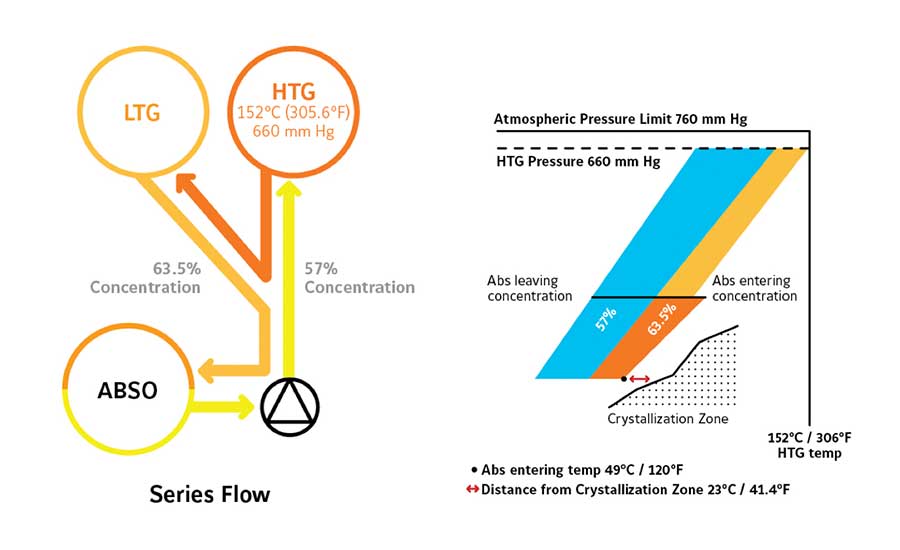 FIGURE 5: Typical series-flow configuration*: All of the LiBr solution from the absorber section flows first to the HTG, then to the LTG and back into the absorber section. *Conditions: Chilled water entering/leaving: 12/7°C (53.6/44.6°F). Cooling water entering: 32°C (89.6°F).
Although all conventional double-effect absorption chillers employ an evaporator-absorber, there are three different ways to handle the flow out of the absorber section and back into the absorber section through various piping and heat exchangers.
-
Typical series-flow configuration — The LiBr solution from the absorber section flows first to the HTG, then to the LTG and back into the absorber section (Figure 5);
-
Typical reverse-flow configuration — The LiBr solution from the absorber section flows first to the LTG, then to the HTG and back into the absorber section (Figure 6); and
-
Typical configuration using parallel flow alone — Parallel flow cycle means that the LiBr solution leaving the absorber section is split into two parallel streams. One stream goes to the HTG (high-temperature generator) and the other to the LTG (low-temperature generator) in two parallel streams (Figure 7).
Improvements Obtained By Combining a Parallel Flow Cycle With 2-Step E/A
Double-effect designs operate with a much higher-grade driving heat source compared to their single-effect counterparts. In each type, PTC varies, but the parallel flow design has the lowest values of all types. Using the parallel flow cycle substantially lowers HTG pressure and temperature, but, by combining the parallel flow cycle with a 2-Step E/A, new lows have been obtained (Figure 8). The result is unprecedented lows in LiBr salt concentration during operation, which minimizes crystallization risks and provides other performance benefits.
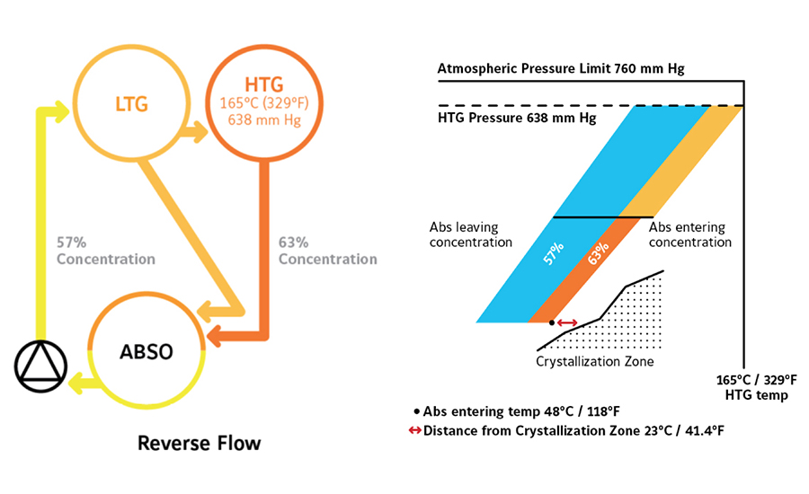 FIGURE 6: Typical reverse-flow configuration*: All of the LiBr solution from the absorber section flows first to the LTG, then to the HTG and back into the absorber section.
Key Benefits: Minimizes Crystallization and Improves Reliability
Note from Figure 8 that the combined design has the lowest entering and leaving LiBr solution concentration percentage from the absorber section. The dilute (weak) solution leaving the absorber section is only a 54.5 percent concentration, which makes it easiest to boil in the generator sections compared to any other cycle. This low concentration also means a relatively lower salt concentration of the LiBr solution enters the absorber, which is very beneficial because this is the line most prone to crystallization. Note in the above graphics that the distance (gap) away from the danger crystallization zone. The distance (gap) from the crystallization for a parallel flow + 2-step E/A cycle is as much as 29ºC (52.2ºF) compared to only 23ºC (41ºF) for other cycles. The wider the gap, the better the protection from crystallization. Clearly, the 2-step E/A + parallel flow design provides the best protection compared to any other cycle. Consequently, the 2-step E/A + parallel flow cycle combination is a simple, yet highly engineered design that provides increased protection against crystallization while avoiding the complexities of using multiple evaporators and absorbers.
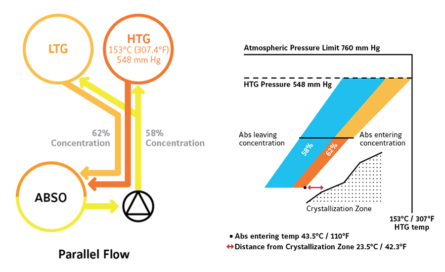 FIGURE 7: Typical configuration using parallel flow alone*: Divides the LiBr solution flow between the low-temperature and high-temperature generators into two parallel balanced paths.
Other Benefits
The same technological combination not only contributes to reliability but also enables high efficiency and other benefits.
-
Circulation flow rates drop and coefficient of performance (COP) increases — At 7 percent, 2-step E/A + parallel flow unit has the largest concentration difference across the absorber section, thereby requiring less LiBr solution circulation flow rate, which results in faster start-up time, less driving heat input, and, therefore, high efficiency;
-
Purging frequency is reduced — Note that the unit operates with the lowest temperature and pressure in the HTG section. The pressure in the HTG section is only 540 mm Hg, which is well below the high-pressure limit (trip set point) that is typically set below 760 mm Hg. The concentration of the solution leaving the HTG is less than 62.5 percent, enabling a cycle with the best combination of the lowest HTG temperature, pressure, and concentration. Due to the lowest HTG temperature, the rate of corrosion and therefore the rate of generation or amount of non-condensable gases are lower, thereby reducing frequency of purging (purge/vacuum pump operation);
-
Flexibility to handle reduced water flow or increased delta T with the same absorption chiller model — For large chilled water and cooling (condenser water) systems, the reduced flow (large delta T) on chilled water and condenser water helps save a significant amount of pump energy. That's because flow can decrease and delta T can increase on both the chilled water as well as the condenser water using the same model (Figure 9).
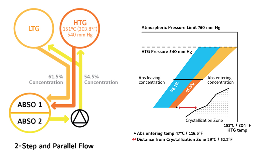 FIGURE 8: Configuration using 2-step E\A + parallel flow*: Combining these two technologies, a two-step E/A and parallel flow design provides the lowest temperature, pressure and concentration. Because this design uses a lower LiBr concentration, it is easier to heat in the generator section. Therefore requiring a relatively lower grade for the driving heat source, providing a high COP.
|
Parameter |
Typical Flow |
Reduced Flow (large ΔT) |
|
|
Conditions: |
Conditions: |
|
Model |
CGN1000EXWH |
CGN1000EXWH |
|
Cooling Tons |
1000 |
1000 |
|
COP (Coefficient of Performance) |
1.40 |
1.38 |
|
ΔP Chilled Water kPa (ft H2O) |
75 (25) |
31(10.3) |
|
ΔP Cooling Water kPa (ft H2O) |
56 (18.7) |
41 (13.7) |
|
Chilled Water Flow m3/hour (gpm) |
605 (2663) |
378 (1664) |
|
Evaporator Passes |
2 |
2 |
|
Cooling Water Flow |
1018 (4481) |
854 (3758) |
|
Absorber + Condenser Passes |
2 |
2 |
FIGURE 9: Same double-effect absorption chiller model with 2-step E/A + parallel flow cycle and can handle reduced flow or increased delta T.
Conclusion
In summary, 2-step E/A technology enhances single-effect absorption chiller performance by improving crystallization protection along with boosting COP and enabling the use of much lower-grade hot water or low-pressure steam as a driving heat source. These benefits crossover to advanced double-effect absorption chillers that take advantage of parallel-flow-cycle technology. In the double-effect cycle, the 2-step E/A and the parallel flow combination optimizes PTC to keep the chiller operating farthest from the crystallization zone. This combination also boosts COP, handles reduced water flow and increased delta T, and reduces purging frequency. All this is accomplished with simple construction that avoids the complexities of other designs using multiple evaporators and absorbers with multiple pipes and zig-zag piping. The end result is greater application flexibility plus an optimum balance between reliability and efficiency, which make these advanced absorption chiller designs more attractive for more applications than ever before.


