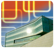
When your project is a facility for studying productivity and building energy systems, expectations for both performance and sustainability are raised. See what else was raised in Syracuse, from the floor plenums to the idea of changing the originally proposed temperature setpoints, to the “cloud” formations of radiant panels used for both heating and cooling.

Figure
1. Schematic
piping arrangement of a cooling and heating radiant panel group.
MEET THE ALL-STARS
Back in June of 2005, Syracuse University announced a team selected to design the SyracuseCoE headquarters. The design team included local and national experts led by Syracuse-based executive architect, Ashley McGraw Architects, assisted by world renowned design architect Toshiko Mori. Arup’s New York City office performed structural, mechanical, electrical, plumbing, and fire protection engineering as well as the lighting design, and consulted on the facade design, telecommunications infrastructure, and acoustic criteria.Other design team members include LeChase Construction (construction managers), Hargreaves Associates (landscape architect), Stearns & Wheler (civil engineer), John P. Stopen (geotechnical engineer), Peterson Engineers (vertical transportation), O’Brien & Gere (environmental engineer), C&S Companies (commissioning agent), 7 Group (LEED® consultant), Burt Hill (lab planner), and Transsolar (climate concepts).
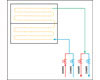
Figure
2. Schematic
piping arrangement of a cooling only radiant panel group.
PROJECT DETAILS
As such, the project had very high expectations. The design team was tasked with creating a 55,000-sq-ft, five-story “tower” and a double height “lab wing” to house their various labs, classrooms, and mechanical spaces. The tower houses the Willis H. Carrier Total Indoor Environmental Quality Lab, a one-of-a-kind lab designed to study human performance and productivity. A biofuels research lab and pilot plant and other advanced labs are being planned for the lab wing.Naturally, the design team was expected to develop a LEED Platinum building and beyond using the USGBC’s LEED NC 2.2 rating system. To top it off, the new headquarters had to be a living and breathing building. The program had to be flexible and, in turn, the building systems and controls had to be flexible to keep up with the changes.
So, the challenge the design team faced was how to contribute to the creation of a living, breathing, low-energy building. In the end, Arup chose to design a displacement ventilation air delivery system. One AHU supplies all the air to the tower spaces at the ventilation rates prescribed by ASHRAE 62.1-2004 and LEED NC2.2.
Air is distributed in two primary ways: either through a raised floor plenum with displacement ventilation floor grilles, or overhead displacement ventilation fabric ducts where there was no raised floor. The AHU was sized to deliver 100% outside air, treating the air to 62.9°F db and 56° wb. This condition dehumidifies the air substantially by the combined use of a total energy wheel, a passive dehumidification wheel, and a cooling coil to deliver low-level air comfortably to the occupants. Removing moisture from the outside air was also a necessity because of the extensive use of suspended radiant chilled and heating panels.
The SyracuseCoE needed a condition where air did not condense on cold surfaces. Since the building AHU deals only with all the latent loads, the design needed to deal with the extra space sensible loads the ventilation air did not handle. That’s where radiant chilled/heating panels came into play.
ZONE CONTROL
On any sustainability project, getting client approval is always critical. Slight deviations from standard internal room setpoints were proposed in an attempt to reduce loads. SyracuseCoE agreed to the higher internal design conditions than usual. Summer design conditions of 74° ±5° and 70° ±5° in the winter helped reduce equipment size. During design, different options were presented to deal with the sensible loads, including chilled beams. In the end, design architect Toshiko Mori Architects preferred the radiant panels over all the other options because of what could be achieved aesthetically. Building owner Syracuse University liked the idea because of their low energy operation. Panels manufactured by TWA Panel Systems, Inc. were selected because of their various options for panel extrusion profiles and arrangements.
Figure
3. Central
plant schematic flow diagram.
Panels are also grouped in a space to provide zone control for both perimeter zones and interior zones. The perimeter zone panel groups can provide both heating and cooling while the interior zones provide only cooling. The piping arrangements are best described by Figures 1 and 2.
The number of passes of copper tubing, bonded to the backside of the panels, is a factor in achieving the desired output. In this case the panels have either four or five tube passes with outputs of 48 Btuh/linear ft in cooling and up to 198 Btuh/linear ft in heating.
Although most panels have only one circuit of tubing, panels along the perimeter have two circuits. Once circuit is for cooling along the whole length of the panel, and the other is for heating a portion of the panel length closest to the perimeter façade. This arrangement was necessary to try to make the panels look as seamless as possible to the occupant. Otherwise, there would be two distinct panels with a visible seam or joint and additional piping and control elements.
Heating is provided in a perimeter zone while simultaneously cooling is provided in an interior zone. The motorized valves shown in Figure 1 are on/off valves and isolate the service that is not needed. The chilled and hot water loop that feeds the radiant panels are all part of a water-to-water source heat pump system that makes up the building’s central plant.
THE CENTRAL PLANT
The central plant includes seven water-to-water source heat pumps, each providing 265 MBtuh of cooling and 249 MBtuh of heating. The heat pumps are lined up, as shown in Figure 3 so that some can be used for cooling while the others can be used for heating if required simultaneously. When there is a need for cooling, the appropriate quantity of heat pumps on the top end become active and the appropriate isolation valve closes to segregate those units from the other heat pumps on the bottom end. This was dubbed a “sliding valve” header arrangement because the location of the isolation valves slides along the header, depending on how many units are needed for either cooling or heating.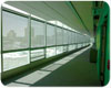
Figure
4 and 5. SyracuseCoE
incorporated a hybrid ventilation design. Each operable window is
equipped with a magnetic contact that indicates to the BMS its
current position. When a window is opened, the BMS closes the zone
air damper to that portion of the underfloor air plenum as well as
the radiant panel zone control valve.
The heat rejection from the heat pumps is accomplished by a closed loop geothermal bore field. Because of brownfield conditions on the site, the need to ship out the contaminants to approved landfills certified to deal with the specific contaminants, and the very high costs to completely remediate it, Syracuse University decided to encapsulate the contamination while minimizing how much was hauled away to landfills.
As such, site real estate was reduced, and we could not drill all the bores needed to deal with all the cooling loads. Therefore, the added cooling tower balances the heat rejection loads and high-efficiency condensing boilers, which were manufactured by Fulton, to make up the rest of the heating loads.
Off the main chilled water loop there is a secondary radiant panel cooling loop separated by a brazed plate heat exchanger. The secondary chilled water loop design temperatures are 62° supplying the panels and 66° leaving the panels. The heating hot water supplied to the radiant panels is at the same temperature as the primary hot water loop temperatures. These elevated primary and secondary chilled water temperatures and lower hot water temperatures work well for a radiant panel system. They also allow the heat pumps to operate at higher EERs and COPs because they don’t have to work as hard to create the more typical colder or hotter water temperatures usually employed in standard chiller and boiler systems. This translates to energy and cost savings in operating the building.
BAS AND NATURAL VENTILATION
Each zone has a space temperature and humidity sensor to help regulate the space conditions. Space dewpoint temperature is constantly being monitored by the Siemens BMS to avoid condensation, which is especially pertinent when operating in the natural ventilation mode.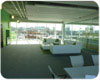
Figure 5
RADIANT PANELS
For added safety, the chilled water piping to the radiant panels is equipped with a surface temperature sensor to prevent condensation on the panel surfaces. If the pipe surface temperature is less than 3° above the room dewpoint, the cooling control valve will automatically close.The panels played an important role in the architect’s plans. Once we agreed on how the building loads would be handled, it set the tone for other aesthetic features. The panel elevations and horizontal mullion locations on the fully glazed south façade were set to match and were coordinated with the primary steel structure that spanned in the east-west building axis. Luminaire locations and elevations were then set to match the panel elevations and were located in between the floating radiant panel groupings, so that we achieved the design ambient levels of 25 footcandles. The sprinkler layout was also coordinated to properly cover the occupied spaces, with heads mounted within the radiant panels as well as above to protect the whole volume.
All in all, this project is a prime example of total design team coordination to meet SyracuseCoE’s needs. Arup worked very closely with Toshiko Mori Architects and with Ashley McGraw Architects. Syracuse University’s office of design and construction and SyracuseCoE also participated heavily during design and construction. All the parameters were then transferred to the builders led by the construction managers, LeChase Construction, who put it all together with high attention to details.
Edward Bogucz, executive director of the Syracuse Center of Excellence in Environmental and Energy Systems said, “The radiant panel system working in conjunction with the underfloor air system, not common in American commercial buildings, allows us to control the thermal environment of the spaces in a unique way. We are in the early stages of learning the operations of this method of space conditioning and look forward to realizing the benefits of improved indoor environmental conditions and lower energy consumption.”
The design team is still waiting to finalize some of the LEED credits. The project is still on track for a platinum rating under the LEED NC2.2 criteria. The systems discussed in this article helped contribute to many of the valuable credits, such as 9 out 10 credits for Energy and Atmosphere credit 1, Optimize Energy Performance.ES
