A WSE generates cold water using only the cooling towers during cool weather. Both systems save energy during cool and cold weather, which is why the term economizer is used.
In the northern portions of the United States, the ASE can usually be effective for more operating hours than the WSE, thereby saving more energy. The ASE is also easier to design, operate, and maintain. So what are the valid reasons to choose the WSE?
Choosing The Waterside Economizer
First, the WSE does not require large outside air and relief air ducts and associated louvers. This would make it a prime candidate for a large historic preservation project where the building envelope cannot be altered.It also may not be practical to create large floor openings in some facilities to accommodate these outside air and relief ducts. And for certain types of facilities, an ASE may cause more energy to be consumed than it might save. This situation occurs when the indoor rh needs to be maintained during the winter and the cost of humidifying additional quantities of outside air exceed the savings for mechanical refrigeration. These applications would include facilities such as data centers and telecommunication facilities.
Finally, the impact of outdoor air on IAQ may be an issue in certain localities. The great outdoors is home to a multitude of airborne particulates such as pollen, spores, mold, dusts, fumes, and smoke. By using a WSE, the amount of outdoor air entering a facility can be fixed at the code-required minimum year round thereby limiting the large quantities of outdoor air admitted during operation of the ASE. High-efficiency filters can also be placed on smaller, dedicated ventilation units.
Unfortunately, hay fever season coincides with the peak annual use of the ASE in many regions of the country. Pollen grains that are transported by air range between 10 and 50 microns in size and can be removed fairly effectively from the supply air with medium-efficiency filters (35% to 45%).
However, hay fever symptoms can appear when the pollen count is as low as 10 to 25, while seasonal peak pollen counts can approach 1,000 or more for a 24-hr period in some areas of the country. A 30% filter can remove 98% of the particles 10 micron and larger, however it can be shown that the pollen count could still theoretically exceed the symptom range in peak season even after being filtered.
If a WSE system is chosen, there are important rules to consider that affect the project's success, including those of a statutory nature as well those of nature itself. The statutory issues can be found in the applicable energy codes and are typically based upon ASHRAE 90.1.
This standard states that the WSE shall be capable of cooling supply air by indirect evaporation and provide up to 100% of the expected system cooling load at outside air temperatures of 50 degrees F drybulb and 45 degree wetbulb and below. The primary issue that nature imposes upon the designer is that water freezes at 32 degrees. Translating this physical fact into steps the designer needs to consider and into features that must be incorporated into the system can be a challenging task.
Estimating The Cooling Load
One issue is calculating the peak cooling load in order to size the water-based, free-cooling system. Since the system will be operating when the outdoor temperature is less than the indoor temperature, except for solar gain there will be a net heat loss at the building's skin.In addition, the minimum outside air brought in for ventilation will work to offset some internal heat loads. In northern climates of the United States, the peak load for the WSE could be two-thirds or less than the peak cooling load for summer operation.
During operation of the WSE, there should be no latent load and this should permit the circulating chilled water temperature to be higher than during normal cooling operation. To maximize the number of WSE operating hours, it may be beneficial to design the system to deliver 50 degree-, 55 degree-, or even 60 degree-chilled water.
It should be cautioned that if this approach is taken, the interior zones may need to be designed for increased airflow capacity. Once the WSE cooling load and permissible cooling supply water temperature have been determined, the system components can then be selected.
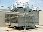
The Cooling Tower
Paramount in this component selection process is choosing and sizing the cooling tower. Intuitively, with the cooling duty less for the WSE system and the towers operating against a much lower ambient wetbulb temperature, it would seem that a standard cooling tower selection would prove more than adequate for the WSE mode.Don't be fooled. The cooling tower selected will most likely be much larger than that selected for the refrigeration equipment needed for peak summer cooling, perhaps 50% or greater. Although the wetbulb design condition is lower, the required approach will be much smaller, making the tower less effective than at summer design conditions.
Make sure that application engineers from several tower manufacturers run selections as the software that local equipment representatives have may not be capable of making selections at low wetbulb temperatures.
The most common types of towers for hvac applications are the induced-draft crossflow and the forced-draft counterflow. The latter type is not well suited for WSE service for several reasons.
First, the fans of a forced-draft counterflow tower are located in the entering cold airstream rather than in the warm leaving airstream. This tends to allow the mechanical section to freeze first. It also increases the probability of recirculation which can work to exacerbate this initial problem.
Recirculation of warm, moist air back into a forced-draft counterflow tower is more probable than for the induced draft crossflow as the ratio of the exit velocity to intake velocity is lower for the forced-draft tower.
As airflow is reduced because of icing on the fan section, the exit velocity is reduced, thereby increasing the chances of recirculation and ice buildup. The fans on a forced-draft tower should never be reversed as this will concentrate moisture on the fans and dampers. Also, most of these towers use centrifugal blowers which cannot reverse the direction of airflow.
The induced-draft crossflow tower operation is much different. As the load reduces and the fans switch to low speed or are shut off, the warm water over the fill is then more likely to fall in a vertical pattern, allowing it to come in contact with the louvers and subsequently melting the ice that tends to form there. The fans and mechanical components are also exposed to warm air at all times that water is flowing, whether it be over the tower or bypassed into the basin.
The buoyancy of this warm air will cause it to rise across the fan and drive system. It is essential that two-speed fans or vfd's are employed to modulate the tower fan speed during winter tower operation.

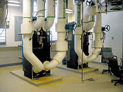
The Heat Exchanger
It is well known that water from an open system such as a cross-flow cooling tower should not be circulated throughout a chilled water system for fear of fouling the entire system.This is well founded, and therefore it is highly recommended that a heat exchanger be used to separate the open tower system from the closed chilled water system. A heat exchanger with a high effectiveness and a small approach temperature such as the plate-and-frame type is preferred.
The heat exchanger is composed of adjoining plates gasketed together and mounted on a carrying bar. Typical plate material is type 304 or 316 stainless steel and for the gasketing, EDPM. A 2 degree approach is common. This requires that the water leaving the cooling tower be 2 degrees cooler than the desired chilled water temperature.
Although a tower water filtration system should always be a consideration, the addition of a plate-and-frame heat exchanger to the system should make it a necessity. Not only is airborne sand and grit a problem in an open tower, but precipitated solids left behind from the evaporation process will eventually make their way to the heat exchanger.
The Dangers Of Ice
Now what about the fact that water freezes at 32 degrees? This can't be changed, but we can make sure that we keep the water flowing outdoors during WSE operation and make sure that all water drains to the indoors when the system cycles off. Preferably, the tower water should not be stored in an outdoor sump in localities where there is a freezing threat.Standard towers for hvac applications utilize a side outlet connection. This configuration will not allow the tower to drain completely, making it important to specify a bottom outlet. All piping located outdoors should be pitched to drain towards the tower.
Just before leaving the heated mechanical room, the piping should rise vertically as it heads towards the tower. This creates a hydraulic "potential" to limit the volume of water that will drain to the tower upon system shutdown.
The distribution manifold in the tower should be specified with a normally open, zero pressure differential solenoid valve that closes whenever the condenser water pump is operating. In the off-cycle, the valve opens allowing the manifold to drain into the bottom of the tower. What to do with all of this water? Placing a sump in a heated indoor environment will solve the problem.
Sump Design
The indoor sump should be sized to accommodate the volume of water in the pipe that drains into the tower plus the volume of water that is in the tower hot water distribution system and resident on the fill during operation. The sump should also have enough water to maintain adequate head pressure at the inlet to the pumps.In addition, there should be space in the sump "above" the normal water level to allow for proper makeup level control. The sump inlet pipe should extend below the normal water level to keep the surface of the water from fluctuating.
Avoid cast iron, float-type, liquid level controls that are normally used on boilers for low water cutoff as they have been known to stick open and cause the system to overflow. The level sensors should be conductivity-activated probe-type coupled with solid-state relay modules with field-selectable sensitivity and adjustable time delay.
Now all the water outside will eventually drain safely indoors. But what about the water when it is outdoors during cold weather? Never modulate the water over the tower during WSE operation. When in the free-cooling mode, the tower bypass valve should operate as a two-position valve. Otherwise, as the valve restricts flow over the tower, it would encourage freezing.
Another feature to consider is having the control system sequenced to reverse the tower fans every so often during extremely cold weather to actually force warm air and water over the louvers to remove ice. This will require a special starter that can switch the leads of the three-phase fan motor.
Eventually the weather will change, and it will warm up outside. If there are at least two chillers, two towers, and two sumps in the system, the heat exchangers can be placed in series with the chillers in the return main in what is commonly called the side car or load-sharing position to permit partial free cooling.
One chiller can be operating, delivering chilled water at the elevated WSE delivery temperature while a tower and heat exchanger are working to cool the system return water before it reaches the operating chiller.
Chiller Start-up
A problem that must be overcome is that of starting a chiller using condenser water from a sump that may be sitting at 50 degrees. Some chiller designs can only accommodate condenser water that is above 75 degrees no matter what the manufacturer states.More than likely, the chiller may be able to handle colder condenser water but not at rated design flow. Therefore, it is critical to have an automated condenser water bypass located at each chiller to modulate flow to keep it online at start-up as the heat rejected is used to elevate the temperature of the sump. The condenser water system needs to have separate discharge temperature setpoints, depending on whether or not it is operating in the free cooling mode.
Another issue to consider is that the pressure drop through the cooling tower, cooling tower bypass, and the plate-and-frame heat exchanger circuits are all different and can cause the condenser water flow rate to vary considerably as the system changes from one mode to another.
Make sure that there are balance valves in each of the three circuits and carefully consider the selection of the condenser water pump to guard against a motor overload condition as it rides out on the pump curve.
Waterside Economizers In Action
The waterside economizer system has been used successfully by URS Corporation's Columbus, OH office on several large commercial projects in recent years.The Hilltop Development Project houses the Ohio Departments of Transportation and Public Safety (Columbus, OH) in two nearly identical buildings totalling nearly 700,000 sq ft. The WSE installed in this facility permitted the 23 floor-by-floor air handlers to be designed without return air fans. Central ventilation air handlers located in the penthouse mechanical rooms were fitted with humidifiers to take care of the load at its source.
Four plate-and-frame heat exchangers and associated cooling towers can generate 5,200 gpm of 50 degree water during cold weather to cool the facility. The four 5,000-gal indoor sumps are configured vertically to facilitate operation of the level controls and are constructed of fiberglass for longevity. The sumps are located in a two-story mechanical room in each building, which is situated below the cooling towers and is elevated above the condenser water pumps.
The On-Line Computer Library Center (OCLC) (Dublin, OH) also utilizes a WSE system. This project involved converting a warehouse to office space with a new intermediate slab, raised access floor, and indirect lighting.
As a result of these features, the slab construction had to be made as thin as possible. This was done with a reinforced, flat-slab concrete floor system that is only 8 in. thick. Ductwork could not penetrate this slab within 4 ft of any column line, reducing hvac design flexibility. This made a WSE system a good choice as the large outside air and relief air ducts were eliminated, reducing the large floor penetrations that would have been required on an ASE system.
Conclusions
A waterside economizer system can go a long way in achieving project design goals where an airside economizer is impractical for such applications as data centers, historic buildings, or where structural or aesthetic constraints are an issue.
Although there are many benefits to the system, there are important items to consider when implementing the design. These items include selecting the chilled water temperature, calculating the cooling load, selecting the heat exchangers and cooling towers, and protecting the system from freezing. ES
EDITOR'S NOTE: Some images associated with this article do not transfer to the Internet. To review the figures, please refer to the print version of this issue.

