
Figure
1. Budget
estimating pump head.
Maybe the problem was born in design - overestimating pump head, or a cooling tower that isn’t towering enough. Or it arose in installation - say, misconnected coils. Even then, a fix may create a new water mystery. Get in step with some successful detecting habits to correct the next troubled system you see.
Troubleshooting building systems is a niche business that is immune to the economy or building owner’s operating budgets. When an HVAC system doesn’t work, or doesn’t want to work to the owner’s expectations, the results can be disastrous. For health care institutions, a system shutdown could interrupt an operating room procedure. For an industrial facility, it could mean stopping product production. For an educational facility, it could mean IAQ problems. So what are some of those problematic jobs, and how did they become problems? Here are some of experiences from 40-plus years in the building industry, focusing on central chilled water systems.
How Do System Problems Start?
I believe most problematic systems originate in the design phase of a construction project, due to an inadequate design process. Every HVAC system design should start with a single-line flow diagram in the conceptual/schematic phase.At this early stage of the building program, the design engineer can write a sequence of operation even if the designer has not firmed up the chilled water system capacity. Having thought through the design, sequence by sequence, the engineer is able follow the chilled water flow through the system, adding control devices as the written sequence is documented.
Figure
2. Cooling
tower and pump installation net positive suction head (NPSH).
At that time, I couldn’t ask anyone in the office, “Now, how did we do this the last time?” This was a first of its kind, one-million-sq-ft facility that could have been conventionally designed with 2,000 tons of peak chiller capacity but instead was designed with a 600-ton chiller in series with two 300-ton chillers and three thermal storage tanks, each with a capacity of 275,000 gal for cooling that would become thermal heating storage (no boiler or utility steam) in the heating season.
I was confident the design would work. When the time came for the system to be commissioned (before the word commissioning was coined), the process went smoothly as I worked with the automatic temperature control (ATC) and TAB contractors. Today, computer-aided software has replaced paper and pencil for creating flow diagram sketches (refer to the “Back2Basics” series for 21st-century flow diagram technology), but the designer should still start with a system flow diagram.
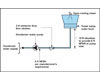
I approach troubleshooting as if I were designing the chilled water system way back in the design phase. It is also important to note this same ATC flow diagram has a second application when troubleshooting/assessing water balance. Just like when I sketched out the ATC system flow diagrams as the design engineer, I would copy the diagram and re-use it to begin plugging in the pressure drops throughout the system to come up with my total chilled water pump head. Figure 1 is a computer software version of this concept and a document that can be forwarded onto the TAB firm in the construction phase. Armed with these two troubleshooting tools, the ATC flow diagram and a TAB flow diagram, I’m ready to begin troubleshooting.
Don't Underestimate the Consequences of Overestimation
Next to not using a system ATC flow diagram in the design phase, the most common issue to troubleshoot, which starts in the design phase and ends up as an inefficient pumping design, is caused by designers who overestimate the pump head. Frequently, designers think bigger is better, but more often than not, overdesign can lead to operational issues and increased energy consumption. A guide to use when sizing a chilled water system is to figure the total pump head will be around 60- to 70-ft pump head. When I see pumps heads closing in at 100 ft - or worse yet, 200 ft - I’m pretty sure I will find a lot of balancing valves substantially closed or maybe just one substantially closed balancing valve on the pump discharge.Some engineers will tell you it is better to oversize pump heads in VFD systems and be safe then to undersize and come up short on chilled water flow. That position is fine if the design engineer is paying the extra money it takes to furnish and install a 100-hp motor (motor, starter, wiring, etc.) when a 75-hp motor would do. I have had the opportunity to design some very large building HVAC systems and re-engineer other very large systems over the years, and I have never designed a chilled water system over 125-ft pump head. At the same time, I have retro-commissioned several chilled water systems that initially ranged from 150 to 290 ft of pump head and got them down under 125 ft without compromising chilled water performance. When assessing these multiple central chilled water systems, I found them to be in the range of 0.25 to 0.35 hp/ton, and got them to operate under 0.1 hp/ton. A good troubleshooting rule of thumb is 0.05 to 0.1 hp/ton.
Is Your Cooling Tower Tall Enough?
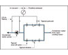
A third troubleshooting problem that starts in the design phase is when the engineer fails to recognize the importance of open cooling tower height in relationship to its condenser water pump. Centrifugal pumps require a net positive suction head (NPSH) to ensure a minimal pressure on the inlet of the pump. In addition to minimal inlet pressure, the designer needs to calculate the pressure loss from resistance of the system via pipe friction loss, and, most importantly, the pressure drop of the inlet strainer (Figure 2).If the engineer does not position the open tower water sump substantially above the pump inlet, the pump will operate in a vacuum condition at its inlet. When troubleshooting this type of installation, my first recommendation is to raise the cooling tower, which probably won’t happen for a variety of existing conditions once the system has been installed.
Figure
3. Duplex
strainer with compound gauge.
The second suggestion is to install a compound gauge (Figure 3, duplex strainer with compound gauge) which will read from inches vacuum to zero to psig. This gauge should be manifolded to be capable of reading before and after the strainer using the same gauge. Monitoring the gauge reading will allow the facility person to switch from the dirty strainer to the clean strainer as the gauge begins to show signs of the condenser water system pressure going into a vacuum condition at the pump inlet.
Installing the Problem
Troubleshooting problems don’t always originate in the design phase and manifest themselves as full-blown calamities. Experience has shown me this fourth issue occurs probably once out of every 25 chilled water coil installations: chilled water coil piped incorrectly on the job site. The results is about a 20% inherent loss in coil cooling capacity (Figure 4) when the chilled water supply is connected on the upstream airside of the coil and the chilled water return connection is piped to the downstream side of the coil.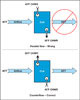
Figure
4. Right
and wrong coil connections.
The same issue occurs with water-to-water heat exchangers that do not have counter-flow between the condenser water and the chilled water. Again, this deficiency may surface when troubleshooting the heat exchanger. On one occasion, we found the problem while retro-commissioning a primary-secondary-tertiary pumping system that was initially designed with 0.32 hp of pumping. We got the pumping energy down below 0.1 hp/ton and re-piped the water-to-water heat exchanger. You could say it was a win-win.
Where'd All the Water Go?
Occasionally, we will tune up chilled water systems by implementing the corrective actions discussed herein, and when we do this, a fifth problem occurs - namely, the “where is all this water going?” dilemma. What I mean by this is that when rebalancing the system, we cannot account for a percentage of the chilled water flow. When this occurs, we find we need to be extra vigilant in documenting piping supply and return connections along the chilled water distribution system.In each case where the system was handling more water than we could account for via flowmeters, we found unrecorded bypass connections between the supply main and the return main. One installation had a dozen unrecorded bypasses, while a second system had ten. My only answer to these engineer-designed and unrecorded bypasses is that they were probably installed to allow flushing of segments of the pipe distribution during the construction phase and, unfortunately, remained in operation after the owner took occupancy. From a troubleshooting point of view, it is something I look for now that I would not have thought to consider in the past. I guess that is what is meant by the saying, “With age, comes experience.”
A sixth troubleshooting challenge is when a second chiller plant is furnished and installed within a facility to provide additional cooling capacity because the existing chiller plant can’t handle the load. In each case, the application was a health care institution, and the need for additional air conditioning stemmed from the age of the hospital dating back to the 1960s and 1970s, when some sections of the hospital were not fully air conditioned.
As each of these facilities received renovations, upgrades, and building additions, the new projects were fully air conditioned. Often, the existing chilled water plant did not have the space to accommodate future equipment expansion, so a new location was selected. The new chilled water system was designed to handle the new addition and/or renovations and was also tied into the existing chilled water plant to work in parallel. The results were less then successful, and so I was contracted to troubleshoot each of these installations. Starting with a flow diagram and surveying the system distribution, the solution was the same. The cross-connection of the supply of chiller plant 1 to chiller plant 2 was done incorrectly (connected to the return main by mistake). So after several years of limited chiller plant performance, a solution was found.


