
Figure
1.
Atria typically consist of architectural designs that
cannot be characterized by algebraic equations.
The authors walk us through the process - and more importantly, where the pivotal smoke control design moments should fall within the larger design/construction process. See who needs to be involved in smoke control along the way, how to split up the special inspection, and why going “Hollywood” isn’t the best idea for the final acceptance test.
With building owners looking to go green and trying to maximize energy efficiency, atria are becoming increasingly common as architects look for ways to passively light their buildings. Large, open spaces spanning multiple floors are not only aesthetically pleasing but are the perfect method for introducing daylighting to interior spaces.
Unfortunately, atria, more often than not, require a smoke control system that comes with its own set of challenges. The systems can be complicated in every respect, as their design, installation, and commissioning requires architects, mechanical, electrical, and fire protection engineers to coordinate their system designs. While this article focuses on atrium smoke control systems, many of the recommendations described in it are appropriate for any smoke control system.
As model codes (International Building Code, NFPA 101 - Life Safety Code, and NFPA 92B) have evolved toward performance-based smoke control systems, the role of the fire protection engineer has increased, in part due to the inability of the prescriptive calculations to accurately predict smoke production rates for geometrically complex atria.
This performance-based approach allows greater flexibility but requires specialized expertise in fire protection with a strong background in fire dynamics. Many fire protection engineers have this specialized expertise and can assist HVAC engineers of record in areas such as rational analysis, design fires, computer fire modeling, the integration of fire protection and fire alarm systems, and development of the overall smoke control system concept/approach through installation and implementation. The following is a summary of critical steps recommended for a successful smoke control system.
Step 1 - Applicable Codes
The beginning phase of smoke control design is not dissimilar to other systems. Determining the applicable codes which will ultimately be the driving force of the design is a necessity. The International Building Code (IBC) and NFPA 92B, Standard for Smoke Management Systems in Malls, Atria and Large Spaces, are both widely adopted throughout the United States and internationally. The time that a smoke control system is expected to maintain a tenable environment can vary significantly based on whether or not NFPA 101, Life Safety Code, is applicable, as a timed egress analysis may be required. Some local jurisdictions also have additional smoke control system requirements for floor-to-floor smoke control, stair pressurization, and elevator shaft pressurization. Pressurization smoke control systems manage migration by creating pressure differentials across smoke barriers. These smoke control systems still require most of the steps to be followed for a successful smoke control system.Step 2 - Design Fire
The designated design fire is a major factor in the smoke control system design. The design fire criteria outline the type and size of fire that the smoke control system is designed to incorporate. Fire protection engineers’ background in fire dynamics, material properties, and understanding the sprinkler effectiveness on fires make them uniquely qualified to work with the design team and owners to determine reasonable severe case design fire scenarios. Prescribing a realistic design fire is essential to being certain that the smoke control system is sufficient to provide a safe environment for occupants in the building.Step 3 - Rational Analysis
Understanding the design fire and how the applicable codes affect design allows the design team to move in the correct direction when beginning the code-required rational analysis. The rational analysis is a supporting document that is submitted along with the construction documents that outline the design parameters and key assumptions associated with the smoke control system design and approach.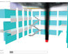
Figure
2.
Graphical output of a fire model simulating a fire within
an atrium.
Utilizing the prescriptive algebraic equations in NFPA 92B to determine the quantity of smoke exhaust needed may seem simple enough to some; however, it is of the upmost importance to realize the limitations and appropriateness of these equations. Simply by looking at NFPA 92B Section 6.2.1, the quantity of mass produced by the smoke plume is based on the size of the fire and the distance from the fire to the smoke layer. From this mass production rate, the density of the smoke is evaluated and, in turn, the volumetric flow rate (the amount of exhaust needed) is determined.
What is important to note is all of the potential factors that these equations do not account for. Complex geometries, toxicity of combustibles, exhaust, and supply air locations relative to the fire, as well as makeup air and its impact on air entrainment all have a large impact on how much exhaust should be provided and how effective a smoke control system design will be. While a design that follows these prescriptive calculations could result in a working smoke control system, it is also possible that the design is potentially over or under designed or just might not be effective in a real world fire situation.
Step 4 - Computer Modeling
To ensure that a smoke control system is successfully designed, a performance-based-design (PBD) approach utilizing a computational fluid dynamics (CFD) fire model called fire dynamic simulator (FDS) is often used. The FDS model evaluates a smoke control system by inputting the atrium geometry, exhaust, and supply locations as well as the specifics of the fire, into a three-dimensional computer model. A hazard analysis can then be completed by evaluating the impact of the design fire and smoke on building occupants located within the atrium.The hazard analysis allows the design team to evaluate the effectiveness of locating exhaust inlets at various locations as well as the impact that supply air can have on smoke migration. By using a fire model, the user can modify exhaust quantities and locations with relative ease to evaluate the effectiveness of different smoke control designs. The data that is obtained from the simulations is then used to evaluate occupant’s visibility through smoke and their exposure to temperature and the toxic byproducts of the fire. Because use of the model requires an understanding of what items are being modeled, as well as how real-world items are converted into appropriate fire model input, it is important that the model user have a strong background in fire dynamics.
Undoubtedly, the use of a fire model requires far more initial effort from the design team than a smoke control system designed purely to the prescriptive calculations in earlier editions of the IBC or NFPA 92B. The key advantage over the prescriptive approach is knowing that the designed system will work and how to make a more efficient, less costly, effective smoke control system. The three-dimensional model shows the actual geometry of the atrium, exact exhaust, and supply air locations, the toxicity and thickness of the smoke, and environmental parameters, and it demonstrates whether or not a specific design works as it was intended.
The data from the fire model should be used in the creation of the rational analysis and should provide a set of parameters to be measured and tested in the field during construction to ensure the built atrium is consistent to that of the fire model. These parameters often include airflow measurements at the face of exhaust and supply locations. The end result is a smoke control system that the design team has confidence in as a building begins construction.
Step 5 - AHJ Agreement
The use of PBD and FDS to establish design parameters for smoke control systems is an approach that has been used on numerous buildings in the past several years. While FDS has been shown to be very well suited for this application, the relative infancy of fire models requires an upfront approach with building and fire officials. Holding early discussions with officials to discuss the parameters and assumptions of the model, establishing pass/fail criteria, and agreement on the testing protocol for the smoke control system is a key step towards obtaining approval from the authorities.Having a qualified fire protection engineer who understands the concept of a performance-based approach and the use of a fire model can be important in establishing a comfort level with the officials who may have little expertise in this area. Because the use of the program requires a strong technical background, it is not uncommon for authorities to request a qualified third-party (peer) reviewer to verify the proper use and appropriateness of the fire model.
Step 6 - Construction Schedule
A properly designed system is only half the battle in creating a successful smoke control system, and it is not uncommon to see aspects of the design simply overlooked during construction, especially when there is a looming deadline. Ensuring that the smoke control system is installed and functions as designed all begins with reviewing the proposed construction schedule. Adequate time must be allotted for pre-testing the systems components and performing the required special inspections. The special inspection process is a code required step in any smoke control system design that is sometimes overlooked and enforced even less.
Figure
3. Potential
applicable codes (IBC, NFPA 101, and NFPA 92B).
Step 7 - Special Inspection, Part 1
The special inspection can be completed by a single person or team of people; however, expertise in fire protection engineering, mechanical engineering, and a certified air balancer are required. A special inspection should occur twice during construction: first, during erection of the ductwork and prior to its concealment, for the purpose of leakage testing and documenting device locations.Step 8 - Pretesting
Prior to the second part of the special inspection, the contractor should perform a pre-test of all system components and their interactions relative to the building’s smoke control system. With the smoke control system design and criteria approved, the pre-test, special inspections, and final acceptance testing is focused on verifying the approved design. This is done in three major steps, which typically include:- Component testing and verification (fan belts, dampers, etc.)
- Testing of sequence of operations
- Actual field measurements (air velocities, flow pressure differentials, door opening forces, etc)
Step 9 - Special Inspection, Part 2
After successfully working out the issues encountered during the pre-test, the second part of the special inspection will occur prior to occupancy and near completion of construction. At this time, pressure differentials should be measured at door locations and across smoke barriers, and the door opening forces should be confirmed. Airflow measurements should be obtained from each exhaust and supply fan and any passive supply air should be verified as well. If the system was designed utilizing a fire model, these measurements would be compared to what was observed in the model. Detection devices as well as any devices designed to initiate the activation of the smoke control system should be tested not only for their activation, but to confirm the proper integration and operations of the building’s systems and components.Step 10 - Acceptance Test
The final step for any smoke control system is the final acceptance test performed by the local building officials and/or fire department. Each jurisdiction has its own approach for testing a smoke control system, ranging from testing all the items performed during the special inspection to initiating a single device and confirming sequence of operation. The use of cold smoke or “Hollywood” smoke is not recommended when testing the smoke control system, since the cold smoke will not have the same physical properties as a more buoyant hot smoke that would be present in a fire.Consequently, cold smoke could potentially show a properly designed system as failing and poorly designed system as passing. Even with these inaccuracies, some jurisdictions still choose to utilize cold smoke, and as such, the limitations of the cold smoke test and their usefulness need to be clearly understood. Cold smoke tests used as major criteria for smoke control system testing should be avoided wherever possible. Regardless of how thorough the fire department is with their testing, a properly designed and installed smoke control system that has been properly tested should pass every time.


