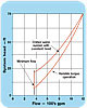
FIGURE 1. Chilled water system head curves.


Designers need to have a way to compute part-load energy consumption scenarios. However, the data aren’t always available. Here, we look at why some good math is worth the effort.

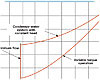
FIGURE 2. Condenser water system head curves.

Wire-to-Shaft efficiency for variable speed, centrifugal pumps defines the percentage of power inputted to the pump motor that results in energy in the pump shaft. Figure 1 describes this; it is also obvious that it is a blend of the efficiencies of the motor and VSD. It is not a simple multiplication of individual motor and drive efficiencies but one efficiency that is affected by the actual brake horsepower on the pump shaft, from minimum speed to full speed. The wire-to-shaft efficiency is determined by the following formula.

WSE = Pump bhp · 0.746 · 100 % (1)
                    Input kW


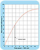
FIGURE 3. Wire-to-shaft efficiency curve.

It is difficult to determine wire-to-shaft efficiency in the field, as you must measure the pump brake horsepower (hp) and that requires a dynamometer. Wire-to-water efficiency includes the efficiency of the pump, and it is measurable in the field, Figure 21. Its equations are:
WWE = WSE % where Pn is the pump efficiency as a decimal (2)  
                Pn
Or:
WWE = Q (gpm) · H (ft.) (3)
              53.08 · Input kW


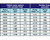
TABLE 1. Comparison of brake hp and pump speeds.

where Q = flow in the system in U. S. gpm

H = net pumping head in ft. measured by the differential pressure transmitter connected across the pumping system headers. The suction and discharge headers must be the same pipe size.

kW = power input to the VSDs for the pumping system as measured by a Watt transmitter.

Wire-to-water efficiency has been used for programming pumps, but it has been replaced by pump input kW that does not require the differential pressure transmitter for measuring pump head.


Figure 4.

Centrifugal pumps are usually considered variable torque machines where the torque required to turn the pump varies as the square of the speed.

M1=S12where M is the torque and S is the pump speed (4)
M2S22

This assumes that the pump performs in accordance with the affinity laws for centrifugal pumps that state that the head on a pump varies as the square of the pump speed. Such is not the case for most variable-speed chilled water or condenser pumps where a constant head exists in the water system. For chilled water systems, a differential pressure is maintained on the system to provide pump head for a terminal unit and its piping and control valve, Figure 3. The constant head in a condenser water system is the lift over the cooling tower plus the friction loss in the chiller condenser, Figure 4. Why is this important?
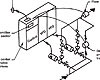
Figure 5.

It is important since this added head no longer allows the pump to operate as a normal variable torque machine. Figure 5 describes the system head curve for a 600 ton, 1,200 gpm chilled water system operating with a fixed differential pressure of 15 feet and a total pump head of 75 ft.; it also includes a curve for a 1,200 gpm system and 75 ft. without the differential pressure and operating with normal variable torque pump performance. The curves begin at 360 gpm and 30% speed, minimums for most chilled water systems. Only one chiller is shown to simplify the calculations. Table 1 provides the actual data for these curves and demonstrates the difference in pump speed and brake hp for the two curves.

Figure 4 describes a condenser water system utilizing variable speed pumps on an installation with five 600-ton chillers. In most cases, there is little energy savings in making condenser pumps variable speed. The pump energy saved is often less than the added energy consumed by the chiller with variable flow in its condenser. The only variable head is the system friction; in this instance, this is 35 ft. Only when there are a number of chillers and a sizeable amount of system piping friction due to remote cooling towers can variable speed be justified.
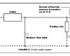
Figure 6.

As shown, the constant head is the lift over the cooling towers plus the friction loss in the chiller condenser. Figure 6 illustrates the system head curve for the condenser water system as well as a similar pump curve for the pump operating as a variable torque machine. Table 2 describes an even greater disparity between the two system head curves for condenser water than that in Table 1 for chilled water. There are only five flows in Table 2 since there is constant flow in the chiller condensers, and five chillers staged on and off with the load on the chilled water system.

Figure 7.

It is obvious from the data in Tables 1 and 2 that the wire-to-shaft efficiency curves for many HVAC water systems are different than those for variable torque operation. Unfortunately, there is no known published data for a wire-to-shaft efficiency curve for a pump operating at higher heads than those for true variable torque operation. The wire-to shaft efficiency for these higher heads should be greater than hp horsepowers at reduced speeds.

TABLE 2. Comparison of brake hp and pump speeds.

Table 3 provides wire-to-shaft efficiencies at various speeds and Figure 5 is the resulting wire-to-shaft efficiency curve for a 30 hp high efficiency, open frame, drip-proof motor that would be required for the above chilled water system.

This data is from the author’s experience with variable-speed pumps and VFDs. It should be replaced by a curve based upon the actual brake horsepowers and speeds of the pump under evaluation. One reason for publishing this article is to encourage people in the VSD industry to develop data for such hybrid pump operation so that HVAC engineers can compute energy estimates for variable-speed pumps with reasonable accuracy. The brake hp and pump speed data in Tables 1 and 2 for the chilled water system and for the condenser water system should be adequate for the computation of these wire-to-shaft efficiency curves.

TABLE 3. Wire-to-shaft efficiencies.

Since almost all new chilled water pumps are now variable speed, it is imperative that the procedure for computing part-load energy consumptions be readily available with accurate data on the wire-to-shaft efficiency for the known motor size and type, pump speeds, and brake hhp.

Reference:

1. Rishel, Durkin, and Kincaid,HVAC Pump Handbook, McGraw Hill Companies, New York City, NY, 2006, page 299.