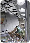
FIGURE 1. A natural ventilation system meets the California Academy of Sciences’ space cooling needs.
When visitors enter this academy’s new home, they won’t only see thousands of specimens and creatures on display. An overtly sustainable design approach - including HVAC that smartly blends natural ventilation and radiant systems - will be on display as well. The way the system adapts to recent and current conditions is as much a key as the equipment itself, so follow it from the CFD to the details adjusted on-site.
Founded in 1853, the California Academy of Sciences is the largest cultural institution in the City of San Francisco, one of the 10 largest natural history museums worldwide, and it has a mission to explore and explain the natural world. The original Academy complex was located in Golden Gate Park and consisted of 12 different buildings constructed over 80 years, with the first constructed in 1916. There was never a master plan for the site; therefore, over time, the complex became inadequate to meet the Academy’s high standards of excellence in research and education. The earthquake of 1989 also caused significant damage to some structures, forcing the closure of sections over time.
BUILDING DESCRIPTION
The new California Academy of Sciences building is opening in September 2008. With an anticipated annual attendance of 1.6 million, the new 410,000-sq-ft structure will house 18 million natural history specimens and more than 10,000 living specimens. With its undulating green roof, the building is fast becoming an iconic landmark in San Francisco.The building consists of five floors, two of which are below-grade. The lower basement level covers only the southern half of the building footprint and contains research, collections, and administrative areas. These spaces are repeated on each floor. The upper basement level includes water-based exhibits (living Coral Reef, Water Planet, California Coast, and a four-level rainforest exhibit) and support spaces.
From the ground floor up, the Academy appears as four, rectangular cornerstone structures reminiscent of the old Academy arrangement. These structures contain the research, collections and administrative areas, exhibits, retail, dining, and conference facilities. Glass walls and an undulating, 2.5-acre native green roof - representing the seven hills of San Francisco - enclose the volume between the cornerstone structures. Included within are the two large spherical volumes (rainforest and planetarium), a 6,000-sq-ft glass piazza, and 38,000 sq ft of flexible exhibit space. As the executive architect Renzo Piano has described it, the green roof design is like “metaphorically lifting up a piece of the park and putting a building underneath.” The rainforest and planetarium form the two larger of the seven mounds that represent the topography of San Francisco.
SUSTAINABILITY AND ENERGY GOALS
Designed to meet the highest standards of environmental excellence, the new Academy is striving to receive a LEED® Platinum rating from the USGBC and is also a city of San Francisco Department of the Environment green building pilot project. The building will be an exhibit in its own right since the public will be able to see many of the principles of sustainable design and operation, energy performance and production, water and IAQ, sustainable collections management, and the living roof.The new Academy’s chilled water is generated by three efficient, 240-ton McQuay centrifugal chillers and circulated by a constant flow primary / variable flow secondary pumping system. This system serves both the building cooling system and the exhibit life support system (LSS) cooling demands.
Condenser water is cooled via three Baltimore Aircoil closed-circuit, indirect evaporative cooling towers. While most of the cooled tower water feeds directly into the chiller condensers, some is routed through the building to serve AHU coils and to absorb heat rejected from refrigerators and freezers.
Six 2,000 MBtuh condensing boilers from HydroTherm generate heating hot water which is then distributed via a variable flow, primary only pumping system.
Sixteen custom Governair AHUs have been strategically located within internal mechanical rooms - some spanning multiple floors - so as to avoid interrupting the green roof. These units, in conjunction with an array of variable and constant volume air delivery systems, provide ventilation and comfort conditioning to most of the spaces. Since the Academy’s life cycle is expected to be at least 50 years, it was relatively easy to justify the added first cost of energy saving components such as condenser water cooling coils, flat plate heat exchangers and enthalpy wheels, carbon dioxide sensors, and temperature- and enthalpy-based economizers.
The research and administration areas at the south facade are conditioned and ventilated via a mixed-mode system involving natural ventilation and finned-tube heating at the perimeter.
MAIN EXHIBIT FLOOR SYSTEM
The first floor exhibit space (38,000 sq ft) was a challenge to ventilate and condition. The goal to maintain monolithic, sheer surfaces within this great volume, coupled with the desire to display the geometry of the green roof above, prevented the design team from using traditional overhead air systems. Instead, the team’s approach was to take advantage of San Francisco’s mild climate, using natural ventilation with supplemental heating and cooling via a radiant floor slab. Solar gains are minimized by the roof overhang and by motorized sun shades protecting some of the glass walls and canopies.Complex analyses were necessary to hone the system design and prove that comfort conditions would be maintained throughout operating hours. In early design stages, Arup used its own thermal analysis software (ROOM) to determine exhibit area surface temperatures, which were then used as input to STAR-CD computational fluid dynamics software. This CFD study looked at a calm day and a windy day to determine indoor air temperatures and velocities and occupant comfort levels. They were also used to determine how much additional cooling was required to augment the natural ventilation scheme. This analysis demonstrated that air movement in the occupied zone would be within acceptable limits, and that good air mixing produces a relatively even air temperature distribution throughout the large volume spaces.
As the building design was refined, Arup used EnergyPlus energy simulation software to evaluate thermal and airflow behavior of the exhibit hall at design conditions. The resultant data allowed the team to determine the most appropriate configuration and control of the radiant floor and natural ventilation systems. The EnergyPlus model results were also used as input for detailed comfort and ventilation effectiveness CFD studies.
The CFD studies proved that at the design summer day (79°F), with the floor slab at 68°, the occupied zone’s operative temperature is expected to be in the mid-70s and the average air velocity is expected to be 35 fps. Likewise, the CFD studies proved the exhibit area would be maintained at an average temperature of 69° and air velocity of 60 fpm in the winter. For both design conditions, these parameters fall well within comfort requirements.
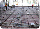
FIGURE 2. More than 100,000 linear ft of tubing was used in the radiant system underneath the main exhibit floor. The system meets the building’s space heating and sup-plemental cooling requirements.
SYSTEM DETAILS
Natural ventilation does the majority of the space cooling, while the radiant slab provides all space heating requirements and supplementary cooling. The massive concrete surfaces exposed to the exhibit area serve as a thermal capacitor, thereby reducing peak loads and ensuring space comfort is maintained. Sun shades on the east and west glass walls and on the north canopy will be activated when the solar intensity high, unless wind speed is excessive.High and low level ventilation openings are located in the glass walls surrounding the exhibit areas. In the colder months, high-level openings are used for background ventilation and avoiding low-level drafts. In the warmer months, both high- and low-level openings are used to maximize airflow and limit space temperatures. Roof vent hatches are also provided at the high points above the rainforest and planetarium. All openings are automatically controlled to adjust airflow and temperature.
On a still day, airflow is generated by stack-effect (warm air rising), due to the height difference between inlet openings in the elevations and roof vents above the rainforest and planetarium. On a day where some wind is present, regardless of the wind direction, a negative pressure is generated at the roof vents and drives the airflow.xhibit space temperatures and wind conditions drive the ventilation sequence. Wind direction determines which banks of dampers operate and the space temperature dictates damper position. Vent operation can be overridden by several means. They will move to a more fully open position if CO2concentration exceeds the space setpoint or if high-level humidity exceeds its allowed limit. Some or all the vents will close if conditions are right for floor condensation, if wind speeds are excessive, or if rain or fog is present.
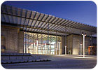
FIGURE 3. The California Academy of Sciences building is hoping for a LEED® Platinum designation and is also a City of San Francisco Department of the Environment green building pilot project.
Powerful exhibit lighting is located above the coral reef and rainforest. When the vents cannot be opened due to one of the aforementioned override conditions, high-level temperatures will rise and trigger the lighting control system to shut off lights, thereby preventing overheating of the space and nearby glass.
The radiant floor is based on an Uponor system built up over a base concrete slab covered by an inch of rigid insulation. Support rails rest on 1 in. strips of insulation and hold 5/8 in. dia hePEX™ plus tubing in place at 6-in. centers. End loops are rounded to maintain 8 to 9 in. dia, thereby preventing buckling. Bolt anchors were fixed to the base slab in between tube rows to allow flexible exhibit ties. The topping pour provided a nominal 2-in. cover, which is necessary to prevent the concrete from cracking.
Approximately 100,000 linear ft of tubing runs in the 38,000 sq ft of concrete slab. Manifolds are located at high level at Level B1. The system is broken into nine independent temperature control zones, so nine sets of valves, pumps, and accessories have been located in the Level B1 mechanical rooms. Each system is a tertiary, constant flow chilled water loop connected to the secondary chilled water loop.
Many of these construction details began on paper but were further developed through on-site mock-ups and close observation of first-in-place assemblies. The snap-in tube rails and 1 in. insulation “spacers” were developed in this manner, as was the method of tying down the loop ends to prevent deflection while the workers walked over the tubes during the topping pour, as it was originally assumed that the topping pour would be worked by machines instead of workers in heavy boots.
The floor operates in cooling mode only when the exhibit area temperature is above setpoint or when the outdoor air temperature is above 77° and rising. In cooling mode, the return water temperature is fixed at 68°. When the outdoor air temperature falls below 64° the radiant floor switches into heating mode. Water temperature is modulates between 75° and 90° as the outdoor temperature drops to the winter design condition. The system changes over from heating to cooling via simple modulation of two-way valves - one at the tertiary chilled water (radiant) loop and one at the associated hot water heat exchanger.ES
Sidebar: California Academy of Sciences Team
Executive architect: Renzo Piano Building Workshop – Genoa, ItalyDesign architect: Stantec Architects – San Francisco
Engineers and sustainability consultants: Arup – San Francisco
Project manager: DR Young & Associates – San Rafael, CA
General contractor: Webcor Builders – San Mateo, CA
Mechanical contractor: Marelich Mechanical – Hayward, CA
Hydronic subcontractor: O’Brien – San Francisco
