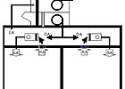
FIGURE 1. Series arrangement of DOAS and terminal equipment.
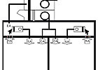
FIGURE 2. Parallel arrangement of DOAS and terminal equipment with individual SA and OA diffusers, a false paradigm.
- Fancoil units (FCU);
- Heat pumps;
- Multi-split units;
- Constant or variable volume all-air systems;
- Active chilled beams, i.e., induction devices2;
- Passive chilled beams;
- Ceiling radiant cooling panels4.
One view is to supply the DOAS air in series with the terminal equipment cooling coil, while the second view is to supply the DOAS air in parallel with the terminal equipment cooling coil. All-air systems are also subject to the differing opinions, at both the central AHU and the terminals. The last three pieces of terminal equipment, beams and panels, can not be arranged in series with the DOAS air, so they are not subject to the differing views. Finally, the first three pieces of terminal equipment generally cannot be placed in series when floor mounted in the individual zones. This article will focus on FCU terminal equipment located in the ceiling plenum.

FIGURE 3. Parallel arrangement of DOAS and terminal equipment.
Terminal Equipment in Series with DOAS
This arrangement is characterized by the requirement that all ventilation air be handled by, or pass through, the terminal devices. A schematic of this arrangement is illustrated in Figure 1.Those who favor this arrangement operate under the false paradigm that a parallel arrangement requires separate DOAS ductwork and terminal supply air diffusers, as illustrated in Figure 2. Note: The false paradigm does not mean that Figure 2 is wrong; rather, it is not the required parallel arrangement since there is a better alternative to be discussed later.
Consequently, those in this camp4identify the following advantages of the series arrangement over the parallel arrangement illustrated in Figure 2:
- Superior thermal comfort;
- Superior IAQ;
- Superior energy efficiency and performance;
- Simpler arrangement;
- Reduced first cost for both labor and materials;
- Ideal for constant volume systems;
- Best choice for low occupancy density spaces;
- Simpler controls;
- Eliminates the need for DOAS terminal reheat;
- Simplifies the selection, performance, and placement of the main diffusers;
- Eliminates the distribution of cold DOAS air to perimeter spaces in the winter.
Illustration of the Performance Difference between Series and Parallel Arrangements
To illustrate the size, energy, and thermal performance differences between the series and parallel arrangements, consider the following 1,000-sq-ft classroom example.Default values from ASHRAE Std. 62.1-2007:
- 35 students, 13 scfm of outside air (OA)/student; or 455 scfm OA;
- Occupant latent load: 7,175 Btuh;
- DOAS supply air (455 scfm) at 45°F and saturated;
- FCU terminal device with DOAS, series or parallel;
- Room drybulb temperature (DBT) maintained at 75° each case;
- Sensible load assumed for each case: 20,000 Btuh;
- Resulting room condition each case: 75° DBT, 56° dewpoint temperature (DPT), 52% rh, 63° wetbulb temperature (WBT), and w=67.53 gr/lbmDA (based upon the DOAS supply air (SA) conditions, flow rate, and latent load)
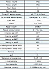
TABLE 1. Coil performance for the parallel FCU.
In the case of the parallel arrangement, that is the space DPT or 56°- using commercial coil selection software5- the parallel performance parameters shown in Table 1 were obtained.
For the series case, the 455 scfm of saturated DOAS air at 45° also removes the entire latent load, and 14,740 Btuh of sensible load, leaving 5,260 Btuh of sensible load for the terminal FCU to handle.
In the case of the series arrangement, mixing the DOAS air and the return air ahead of the FCU reduces both the DBT and DPT seen by the cooling coil. The reduced DBT causes the cooling coil performance to be de-rated, while the lower entering air DPT allows the entering cooling water to be reduced while avoiding condensation and further latent load removal. Employing the identical cooling coil for the series arrangement as illustrated above for the parallel arrangement, the airflow rate must be adjusted to ensure that the FCU SA removes the entire 20,000 Btuh of space sensible load. As the supply airflow rate is adjusted, the fraction of DOAS air (%OA) changes. A few examples are illustrated in Table 2.
When the airflow rate is properly adjusted to meet the 20,000 Btuh sensible cooling load, i.e. 33% DOAS air (OA), the series performance parameters shown in Table 3 are obtained.

TABLE 2. Mixing conditions for the series arrangement with various percentages.
Discussion of the Illustration Results
A coil well-suited for the parallel arrangement was selected and the results presented in Table 1. It may be noted that 420 scfm of warm recirculated room air was handled by the FCU where 5,260 Btuh of sensible cooling was done. The balance of the sensible cooling was accomplished with the parallel DOAS air. For the coil selected, the face velocity was a modest 420 fpm and the airside pressure drop was less than 0.2 in. w.g.When that same coil was applied to the series arrangement where the FCU was required to handle all of the air - i.e., DOAS plus recirculated air - the outcome was bleak. Admittedly, a much larger FCU should have been picked, but to hyperbolize the situation, the parallel unit coil was applied. In contrast to the 420 scfm handled by the parallel arrangement FCU, the series FCU arrangement was forced to handle 1,380 scfm of air at the mixed condition resulting from 33% DOAS air and 67% room air. That represents an increase of 330% in airflow resulting in a face velocity of 1,380 fpm. The increased flow caused the airside pressure drop to increase from 0.17 in. w.g. for the parallel arrangement to 1.4 in. w.g., or an 823% increase in pressure drop. The power increase is 2,700%, something unacceptable.
Of course, one would not allow this to occur, but it dramatically illustrates the impact of using a series arrangement in terms of energy cost. If the FCU for the series arrangement had been increased in size by 330% over the parallel arrangement, the energy issue would be replaced with a first cost issue. In either case, it is desirable to use the parallel arrangement. Finally, under normal part load operating sensible cooling load conditions, the parallel arrangement FCU fan can by cycled as necessary to meet the cooling load, saving fan energy.
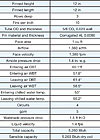
TABLE 3. Coil performance for the series FCU.
Conclusions
For the conditions explored, it is evident that the parallel arrangement is the best choice for DOAS-FCU combinations. While not explicitly discussed in this article, the same can generally be said for DOAS with heat pumps and multi-split units.Some DOAS systems deliver air with a low DPT but DBTs in the 50° to 60°6range. While an example was not presented above, it can be said that elevated DBTs tend to de-rate the terminal equipment less than the low temperatures used in the example above. In any event, the required FCU size is still smaller with parallel than series arrangements, saving fan energy and first cost.
In spite of the conclusions presented, no one solution is best for all situations. Nonetheless, the author recommends exhausting every effort to use the parallel approach before considering the series approach.
Note: The series and parallel terminology used in this article does not apply to fan-powered boxes.ES
Works Cited
1. Mumma, S. A., “Fresh Thinking: Dedicated Outdoor Air Systems,”Engineered Systems, vol. 18 (5) 2001, pp. 54-60.2. Kosonen, R. and F. Tan, “A Feasibility Study of A Ventilated Beam System in the Hot and Humid Climate: A Case-Study Approach,” Building and Environment, vol. 40 (9), September 2005, pp 1164-1173.
3. Mumma, S. A., “Chilled Ceilings in Parallel with Dedicated Outdoor Air Systems: Addressing the Concerns of Condensation, Capacity, and Cost,”ASHRAE Transactions-Research 2002, vol 108 (2), pp 220-231.
4. Personal Conversations with Thom Willie, Atlanta, GA.
5. Coil Selection/Calculation Software, USA Coil and Air Inc., Version 6.
6. Mumma, S. A., “DOAS and Desiccants,”Engineered Systems, Vol 24 (8) 2007: pp 37-49.
