The CHP facility BAS is integrated into the emergency power system,
basing operation of the HVAC system on how many generators are
operating at the time.
Projects of a certain scope can simply take a while, and such is the case with this medical complex. We check in seven years after the site evaluation but still a year or two away from opening. It’s a good time to ask some questions: How do you plan for equipment that isn’t invented yet? How do you keep adjusting design once construction has started? Explore the obstacles - plus intricacies, such as how the BAS works with emergency power - that make such planning anything but child’s play.
The new Children’s Hospital of Pittsburgh of UPMC facility was born out of a merger between the University of Pittsburgh Medical Center (UPMC) and Children’s Hospital of Pittsburgh (CHP). To understand the CHP project, you must first understand the mission that drives patient care at the facility. There is one overarching goal that unites all those involved with the work at CHP: transforming the lives of children through science and compassion. CHP is dedicated to improving the health and wellbeing of children through excellence in patient care, teaching, and research. The dedicated caregivers and staff perform their duties with the utmost respect and tenderness, tending to both the patients and their families. The design of the state-of-the-art hospital had to embody these ideals and enable the caregivers and staff to achieve the mission.
Astorino’s contract as the A/E firm empowered to design a state-of-the-art facility which would house one of the world’s premier health care providers for children, was no small undertaking by any stretch of the imagination.
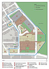
The CHP facility includes nine distinct buildings covering a total of approximately 2.06 million sq ft (47.3 acres) of structures in the current construction plan and the infrastructure for two future facilities. The CHP site plan illustrates the relationships of the buildings and the computer generated aerial view, peeking through the article title, provides an image of the site when complete.
- Clinical services building (CSB – hospital): 1,000,000 sq ft of inpatient and outpatient services and supporting facilities with 300 parking spaces.
- Research laboratory building: 300,000-sq-ft medical research facility with conference center.
- Central plant and expansion: 46,300 sq ft of facility housing steam boilers, chillers, emergency generators, and appurtenances.
- Faculty pavilion: 137,000-sq-ft office facility to house medical and teaching staff.
- Administration office building: 75,000-sq-ft office facility to house administrative and support staff.
- Plaza building: 103,000 sq ft of office space, daycare center, and inpatient family residences.
- Mid-site parking garage: 93,000 sq ft in three stories providing 250 parking spaces.
- Staff parking garage: 297,000 sq ft in eight stories providing 800 parking spaces.
- Clinical office building: 9,500-sq-ft office building.
- Future ambulatory facility: Undefined at this time.
- Future research building expansion: Undefined at this time.
To provide an idea of the facility’s size, the CSB alone was comprised of over 1,700 contract drawings and approximately 2,500 to 3,000 pages of contract specifications. To further illustrate the magnitude of the CSB, consider the following: with over 1,850 air terminal units in the CSB, spending only a mere 10 minutes per air terminal unit, checking schedules for accuracy and completeness against drawings, results in 7.7 weeks of design time per one person.
Creating a state-of-the-art medical facility from the beginning posed many obstacles. The first and most crucial was the selection of an appropriate site. In 2000, the first project site evaluated was a brownfield site located off of 2ndAvenue, along the Monongahela River. In June 2001, Oakland was next evaluated as a potential site. Finally in September of 2002, it was decided that the former St. Francis Hospital site in Lawrenceville would house the new facility.
The Lawrenceville site had the advantages of existing medical facilities that could be reused for much needed program space, and an existing boiler plant that was built less than 10 years earlier. However, demolition of some of the existing facilities (North Wing, North Chapel, Convent, Medical Parking Complex, East Building, Liberace Suite) on-site was required to make room for the critical program space of the CSB and Research Laboratory Building.
Once the site had been selected, the daunting design task could begin. But first, one question had to be answered: what is a state-of-the-art medical facility? As you may have surmised, there were an assortment of ideas and opinions of what constitutes such a facility. Over time, these ideas and opinions developed into a project vision.
Once developed, the project vision met forcefully with the project budget. As owners, contractors, and A/E firms have seen before, the project vision often times falls on one side of the so called “abysmal divide” and the project budget on the other, with owner, contractor, and design team members divided and wondering how we got here. After nearly a year of diligent and painstaking negotiations, a sturdy bridge was formed over the abysmal divide, bringing together project vision and budget.
Before proceeding with the CHP story, a timeline to reinforce the longevity of the project is warranted.
- 2nd Avenue site evaluation conducted in 2000.
- Oakland site evaluation and preliminary design began in June 2001.
- Lawrenceville site selection made and project moved in September 2002.
- Site utility construction packages issued in March 2003.
- Mid site garage package issued in May 2003.
- CSB foundation and underground utilities package issued in November 2003.
- Central plant expansion construction package issued in February 2004.
- Construction and design halted in March 2004, except for the site utility work and the foundation and underground utility work for the CSB.
- CSB design restarted in February 2005 with significant design changes.
- Central plant expansion construction started in June 2005.
- Research laboratory building and staff garage design restarted in August 2005.
- CSB construction documents issued in September 2005.
- Research laboratory building and staff garage construction documents issued in December 2005.
- CSB construction started in January 2006.
- Research laboratory building and staff garage construction started in March 2006.
- Faculty pavilion design started in March 2006.
- Faculty pavilion issued for construction in February 2007.
- Administration office building design started in May 2006.
- Faculty pavilion construction started in April 2007.
- Administration office building issued for construction in May 2007.
- Administration office building construction started in June 2007.
- Research laboratory building occupancy scheduled for July 2008.
- CSB, faculty pavilion, and administration office building occupancy scheduled for May 2009.
Designing a state-of-the-art medical facility seven years prior to its anticipated opening date of May 2009 posed some unique challenges. Just the advancements achieved in medical technology and the local area network (LAN) and supporting data equipment during this time span has been staggering. How do you plan for the mechanical and electrical utilities and special needs for equipment that has not yet been developed?
The nearly seven-year design and construction schedule posed additional challenges of maintaining staff motivation after the initial excitement of the project wore off and fatigue set in. Seven years appears to be a long time for a project. However, when you consider the size, the year delay, changes required for budget constraints, four months for bidding the CSB, and the 3.5 years for the CSB construction, the Herculean effort put forth by the design staff to develop the initial construction documents should not go unappreciated. The design did not stop when the construction documents were issued. Staff was engaged for redesign, accommodating current medical equipment that differed from that of the original design. Staff time was also required for field construction issues and questions.
Compounding the CSB design effort was the early decision to keep the South Wing of the former St. Francis Hospital, joining the new hospital construction to the existing floor-to-floor heights of this facility. The existing Children’s Hospital of Pittsburgh of UPMC in Oakland where ramps were prevalent throughout the hospital drove this decision. Hospital staff negotiating a crib, bed, or wheelchair along with monitors, IVs, feeding pumps, and oxygen bottles over a hospital ramp was problematic even under the best of circumstances. This decision limited five of the 10 floors to 12.5 ft floor-to-floor and the remaining five floors were 14 ft floor-to-floor or less. Most hospital facilities today utilize 15- or 16-ft floor-to-floor for ease of installation, operation, and maintenance of the HVAC, electrical, plumbing, fire protection, medical gas, and telecommunication (telecom) services located above the ceiling.
The key elements for all the HVAC, electrical, plumbing, fire protection, medical gas, and telecom services within the facility were redundancy, reliability, maintainability, and future capacity for growth. Major systems such as chilled water, heating water, steam, normal electrical service, and emergency electrical service were all provided with standby/redundant equipment, so that in the event of a failure of a single piece of equipment, the facility would not have a loss of services.
System capacity for future growth was accomplished by allocating space for equipment to be installed in the future as hospital growth warranted the expenditure. Allocating space for future equipment also meant allocating equipment delivery and move-in paths. In addition, the distribution infrastructure had to be installed to allow for the installation and connection of the future equipment without shutdown of these systems.
Next came the difficult question of how much present capacity and future capacity is required. Having lost the all-knowing crystal ball, the owner and the design team participated in development sessions to determine where the facility will be on opening day and where the facility will be in 10 to 20 years. As most people involved in this process would tell you, it would be easy to resolve this issue with an unlimited budget; however, we had to make the best use of present and future capital.
As with any hospital and laboratory operation, electrical power service was a highly discussed subject, especially after the Northeast Blackout of 2003. The CHP campus is supplied power by three Duquesne Light Company (DLCo.) transformers, fed by three separate service grids interconnected by a 5-kV ring-bus. Any two of the three transformers can supply enough power to operate the entire facility.
Because the facility’s electrical system is energized under emergency power through the normal power circuits, almost all of the mechanical equipment in the CSB, central plant, and research laboratory building is capable of being supplied with emergency power. This affords some unique operational characteristics for the CHP facility. The mechanical systems take advantage of this electrical system design by integrating the BAS into the operation of the emergency power system. The BAS receives a signal from the electrical system to indicate the number of DLCo. service transformers and the number of generators that are operating. Based on the information provided by the electrical system, the BAS determines how many chillers, boilers, pumps, AHUs, and other mechanical equipment to operate based on an extensive priority table. Almost all of the mechanical equipment has been installed with VFDs. This design feature enhances the mechanical system operation on emergency power.
In advance of load shedding by shutting down equipment, the BAS can reduce loads by operating equipment at reduced speed, and thus at reduced capacity. Implementing VFDs also reduces the electrical starting requirements of the generators. This design allows more of the facility to operate under adverse conditions as propagated by the Northeast Blackout of 2003.
Another advantage of this design is that everything happens automatically, providing the facilities operating staff with time to assemble their game plan for a short or prolonged outage. In addition, the BAS affords the operating staff the ability to manually alter the emergency operating characteristics of the facility based on building occupancy, weather, and other factors once the system operation has stabilized.
As the design criteria moved from the central cooling, heating, and power generation systems to the end service equipment, complete redundancy was not going to be cost-effective or practical. Therefore, the driving criteria were reliability and preventing catastrophic system failure. To accomplish these goals, Astorino employed multiple equipment systems that were interconnected. For example, there were seven major air distribution systems developed for the facility. Each system was designed with 15% spare capacity for future growth in HVAC needs. These systems were all designed with multiple AHUs headered together so that a single failure of any AHU would not render a portion of the facility without essential HVAC, except for the hematology/oncology suite that had a single AHU with dual fans. The major air distribution systems deliver over 1 million cfm to provide HVAC to the patient care and support areas.
- Emergency department
- Operating suite
- East CSB inpatient and outpatient services
- West CSB inpatient and outpatient services
- North CSB inpatient and outpatient services
- Hematology/oncology services
- Central sterile and support facilities
Another topic of particular concern for the owner and design team was the multitude of low voltage LAN-based systems that would be employed within the facility. The low-voltage LAN systems include structured cabling, the network, building automation, telecommunication, data, security, fire alarm, medical records, imaging, and other intelligent building systems. Technologies currently available for the built environment offer tremendous value opportunities that are many times unsuccessfully implemented. Typical design and procurement processes for the MEP systems limit the designer’s ability to take advantage of available innovation and integration opportunities. Rapidly evolving system technologies limit both the engineering and the traditional contractor’s ability to perform and properly construct and commission the systems.
The design was structured to add a systems contractor (SC) to install all the intelligent building systems. The SC is responsible for the installation of all low-voltage, network-driven systems. Furthermore, the SC is responsible for the TAB of all MEP systems and providing and managing the systems’ FPT (commissioning). The many advantages to this approach include ensuring construction quality, efficiency, and performance. This approach also supports improved MEP systems construction quality by allowing the MEP contractors to focus on their core competency, such as installing equipment, ductwork, pipe, and wire and conduit, without getting slowed down by networking and integration issues involved with these low voltage systems.
Resolutions to the design and construction challenges presented above, and the multitude of challenges that were not presented, were accomplished through perseverance, dedication, and hard work of many individuals. The success of the CHP project cannot be attributed to any one individual or company; it is the result of the collaboration of owner, design and construction teams.
In reflection, I think all the individuals involved knew that the project must succeed because of its importance to the region’s and the world’s children. There is significantly more to designing and constructing a state-of-the-art medical facility beyond brick, glass, steel, concrete, pipe, duct, and equipment. All stakeholders put forth a monumental effort to make the facility a success. You will not find better pediatric care anywhere, and this will be especially true when the new CHP facility opens in May 2009.
The Children’s Hospital of Pittsburgh advertisement, “If you have kids, be glad you have Children’s,” sums up the new state-of-the-art medical facility. ES

 Bell has over 23 years of experience designing HVAC, plumbing, fire suppression, and automatic temperature control systems for hospital, commercial, institutional, laboratory, residential, educational, governmental, industrial, and high-tech industrial buildings and facilities. His experience includes construction of field engineering-mechanical systems; HVAC systems design and operation instruction; O&M mechanical systems engineer and technician; contractor training coordination; 2,600-ton chiller plant operator; 1,050-hp, 350 °F heating water boiler plant operator; and mechanical systems startup engineer. Bell has also authored two HVAC technical manuals published by McGraw-Hill: